HP Spectre XT TouchSmart Ultrabook 15-4001xx HP SpectreXT TouchSmart Maintenan - Page 75
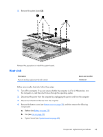
RJ-45 jack cover, Reverse this procedure to install the heat sink.
 |
View all HP Spectre XT TouchSmart Ultrabook 15-4001xx manuals
Add to My Manuals
Save this manual to your list of manuals |
Page 75 highlights
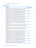
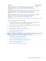
Reverse this procedure to install the heat sink. RJ-45 jack cover Description RJ-45 jack cover Spare part number 701816-001 Before removing the RJ-45 jack cover, follow these steps: 1. Turn off the computer. If you are unsure whether the computer is off or in Hibernation, turn the computer on, and then shut it down through the operating system. 2. Disconnect the power from the computer by unplugging the power cord from the computer. 3. Disconnect all external devices from the computer. 4. Remove the bottom cover (see Bottom cover on page 33), and then remove the following components: a. Battery (see Battery on page 35) b. Fan (see Fan on page 39) c. System board (see System board on page 62) Component replacement procedures 67
-
 1
1 -
2
-
3
-
4
-
5
-
6
-
7
-
8
-
9
-
10
-
11
-
12
-
13
-
14
-
15
-
16
-
17
-
18
-
19
-
20
-
21
-
22
-
23
-
24
-
25
-
26
-
27
-
28
-
29
-
30
-
31
-
32
-
33
-
34
-
35
-
36
-
37
-
38
-
39
-
40
-
41
-
42
-
43
-
44
-
45
-
46
-
47
-
48
-
49
-
50
-
51
-
52
-
53
-
54
-
55
-
56
-
57
-
58
-
59
-
60
-
61
-
62
-
63
-
64
-
65
-
66
-
67
-
68
-
69
-
 70
70 -
 71
71 -
 72
72 -
 73
73 -
 74
74 -
 75
75 -
 76
76 -
 77
77 -
 78
78 -
 79
79 -
 80
80 -
81
-
82
-
83
-
84
-
85
-
86
-
87
-
88
-
89
-
90
-
91
-
92
-
93
-
94
-
95
-
96
-
97
-
98
-
99
-
100
-
101
 |
 |
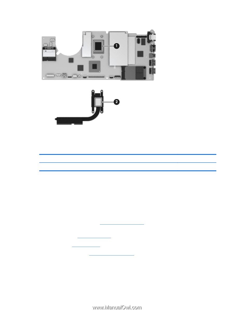
Reverse this procedure to install the heat sink.
RJ-45 jack cover
Description
Spare part number
RJ-45 jack cover
701816-001
Before removing the RJ-45 jack cover, follow these steps:
1.
Turn off the computer. If you are unsure whether the computer is off or in Hibernation, turn
the computer on, and then shut it down through the operating system.
2.
Disconnect the power from the computer by unplugging the power cord from the computer.
3.
Disconnect all external devices from the computer.
4.
Remove the bottom cover (see
Bottom cover
on page
33
), and then remove the following
components:
a.
Battery (see
Battery
on page
35
)
b.
Fan (see
Fan
on page
39
)
c.
System board (see
System board
on page
62
)
Component replacement procedures
67