HP Split 13-f010dx HP Split 13 x2 PC Maintenance and Service Guide - Page 74
RTC battery cable, Volume button board cable
 |
View all HP Split 13-f010dx manuals
Add to My Manuals
Save this manual to your list of manuals |
Page 74 highlights
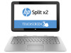
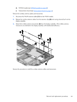
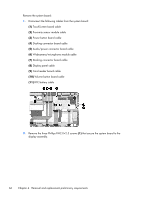
Remove the system board: 1. Disconnect the following cables from the system board: (1) TouchScreen board cable (2) Proximity sensor module cable (3) Power button board cable (4) Docking connector board cable (5) Audio/power connector board cable (6) Webcamera/microphone module cable (7) Docking connector board cable (8) Display panel cable (9) Card reader board cable (10) Volume button board cable (11) RTC battery cable 2. Remove the three Phillips PM2.0×2.3 screws (1) that secure the system board to the display assembly. 66 Chapter 4 Removal and replacement preliminary requirements
-
 1
1 -
2
-
3
-
4
-
5
-
6
-
7
-
8
-
9
-
10
-
11
-
12
-
13
-
14
-
15
-
16
-
17
-
18
-
19
-
20
-
21
-
22
-
23
-
24
-
25
-
26
-
27
-
28
-
29
-
30
-
31
-
32
-
33
-
34
-
35
-
36
-
37
-
38
-
39
-
40
-
41
-
42
-
43
-
44
-
45
-
46
-
47
-
48
-
49
-
50
-
51
-
52
-
53
-
54
-
55
-
56
-
57
-
58
-
59
-
60
-
61
-
62
-
63
-
64
-
65
-
66
-
67
-
68
-
 69
69 -
 70
70 -
 71
71 -
 72
72 -
 73
73 -
 74
74 -
 75
75 -
 76
76 -
 77
77 -
 78
78 -
 79
79 -
80
-
81
-
82
-
83
-
84
-
85
-
86
-
87
-
88
-
89
-
90
-
91
-
92
-
93
-
94
-
95
-
96
-
97
-
98
-
99
-
100
-
101
-
102
-
103
-
104
-
105
-
106
-
107
 |
 |
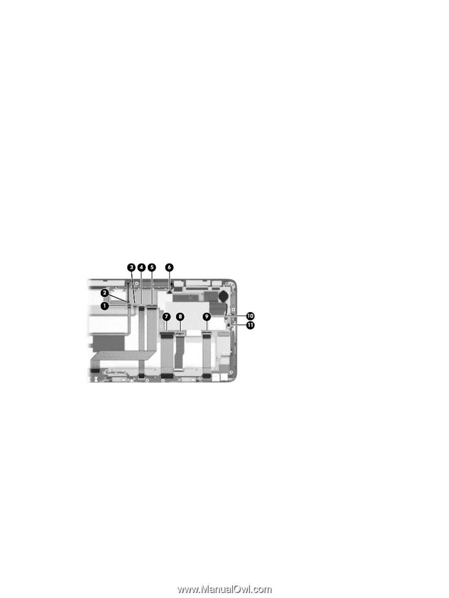
Remove the system board:
1.
Disconnect the following cables from the system board:
(1)
TouchScreen board cable
(2)
Proximity sensor module cable
(3)
Power button board cable
(4)
Docking connector board cable
(5)
Audio/power connector board cable
(6)
Webcamera/microphone module cable
(7)
Docking connector board cable
(8)
Display panel cable
(9)
Card reader board cable
(10)
Volume button board cable
(11)
RTC battery cable
2.
Remove the three Phillips PM2.0×2.3 screws
(1)
that secure the system board to the
display assembly.
66
Chapter 4
Removal and replacement preliminary requirements