HP Superdome SX2000 Site Preparation Guide, Fourth Edition - HP Integrity Supe - Page 19
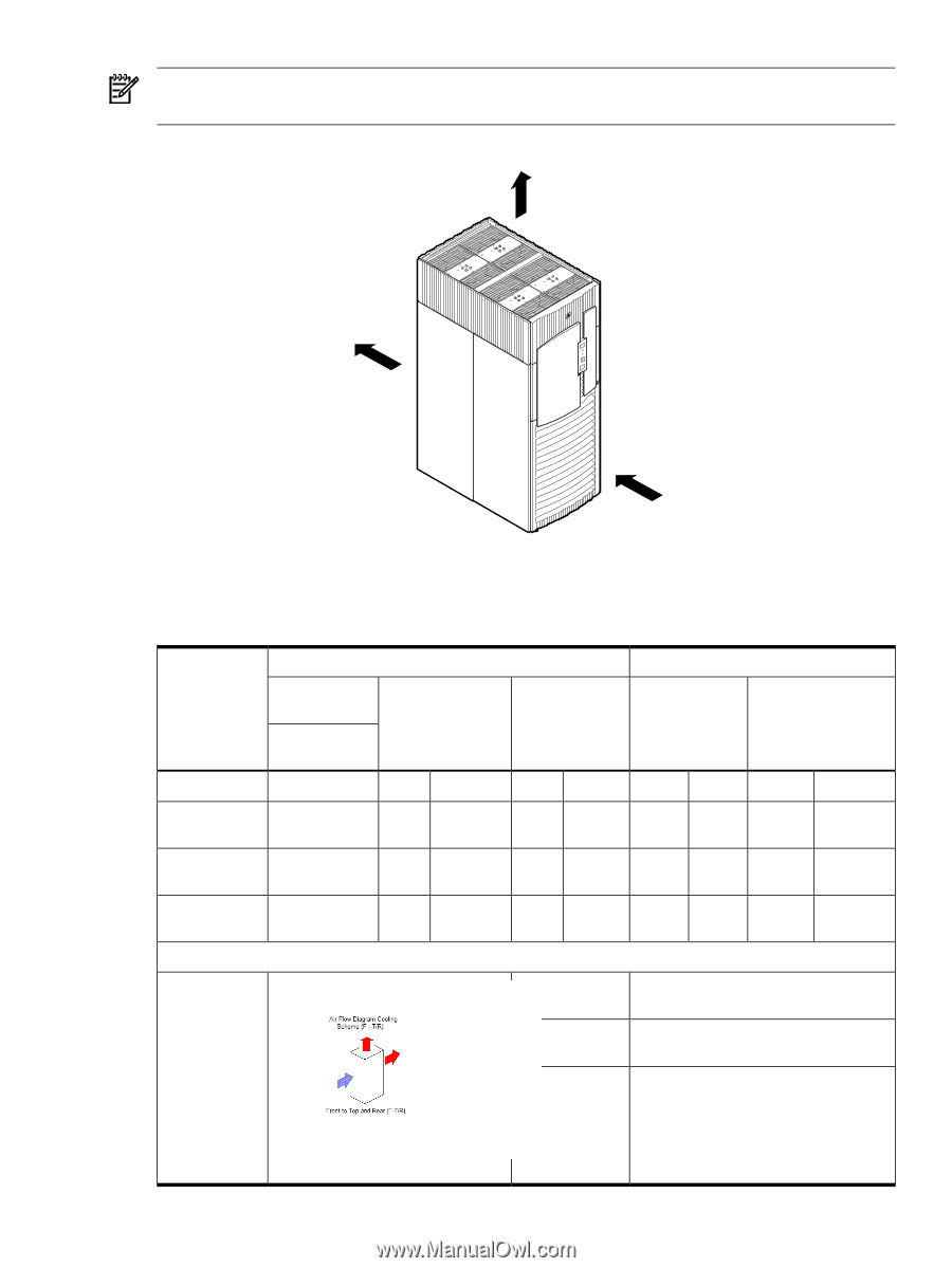
Airflow Diagram, Table 1-17 Physical Environmental Specifications, the top of the system.
 |
View all HP Superdome SX2000 manuals
Add to My Manuals
Save this manual to your list of manuals |
Page 19 highlights
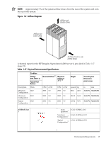
NOTE: Approximately 5% of the system airflow draws from the rear of the system and exits the top of the system. Figure 1-2 Airflow Diagram Airflow exit (2600 CFM) Airflow exit (300 CFM) Air flows front to rear (2750 CFM) A thermal report for the HP Integrity Superdome/sx2000 server is provided in Table 1-17 (page 19). Table 1-17 Physical Environmental Specifications Description Minimum Configuration Maximum Configuration Typical Configuration Condition Voltage 200-240 V ac Typical Heat Release Watts 3423 9130 6968 Nominal Airflow 2 Maximum Airflow at 32oC1,2 CFM m3/hr 2900 5.0 2900 5.0 2900 5.0 CFM m3/hr 2900 5.0 2900 5.0 2900 5.0 Weight pounds kg 926.3 420.3 1241.2 563.2 1135.2 515.1 Overall System Dimensions (W X D X H) in mm 30x48x77.2 76.2x121.9x195.6 30x48x77.2 76.2x121.9x195.6 30x48x77.2 76.2x121.9x195.6 ASHRAE Class 1 Minimum 2 Cell, 4 DIMM, 2 I/O Configuration3 Maximum 8 Cell, 32 DIMM, 4 I/O Configuration3 Typical 6 Cell, 16 DIMM, 4 I/O Configuration3 Environmental Requirements 19
-
 1
1 -
2
-
3
-
4
-
5
-
6
-
7
-
8
-
9
-
10
-
11
-
12
-
13
-
 14
14 -
 15
15 -
 16
16 -
 17
17 -
 18
18 -
 19
19 -
 20
20 -
 21
21 -
 22
22 -
 23
23 -
 24
24 -
25
-
26
-
27
-
28
-
29
-
30
-
31
-
32
-
33
-
34
-
35
 |
 |