| Section |
Page |
| BookInfo - HP VISUALIZE B2000 Owner’s Guide |
1 |
| BookBiblio - HP VISUALIZE B2000 Owner’s Guide |
1 |
| Title - HP VISUALIZE B2000 Owner’s Guide |
1 |
| Subtitle - HP VISUALIZE Workstations |
1 |
| ProductNumber - Manufacturing Part Number:� HP Part No. A5983-90001 |
1 |
| PubDate - Edition E1199 |
1 |
| Copyright - © Copyright 1999 |
2 |
| Year - © Copyright 1999 |
2 |
| Holder - Hewlett-Packard Company |
2 |
| LegalNotice - Notice |
2 |
| Title - Notice |
2 |
| Para - UNIX is a registered trademark in the United States and other countries, licensed exclusiv... |
2 |
| Para - The information contained in this document is subject to change without notice. Hewlett-Pa... |
2 |
| Para - ������������������HEWLETT-PACKARD WARRANTY STATEMENT ����������HP PRODUCT�����������������... |
2 |
| Para - �������� REFERENCE |
2 |
| Para - Part Number A5014-90140 (E1199) |
2 |
| Para - The warranty statement shipped with your product supersedes any and all previous workstati... |
2 |
| Para - Year 2000 Compliance |
3 |
| Para - This |
3 |
| Para - If the Specifications require that specific HP Products must perform as a system in accord... |
3 |
| Para - RESTRICTED RIGHTS LEGEND. |
3 |
| Para - Use, duplication, or disclosure by the U.S. government is subject to restrictions as set f... |
3 |
| Preface - Preface |
11 |
| Title - Preface |
11 |
| Para - This owner’s guide describes how to use your HP Visualize B2000 workstation. This manual a... |
11 |
| Section - Audience |
11 |
| Title - Audience |
11 |
| Para - This guide is intended for HP Visualize B2000 workstation users. |
11 |
| Section - Regulatory and Safety Statements |
11 |
| Title - Regulatory and Safety Statements |
11 |
| Para - See Appendix A for the regulatory and safety statements that apply to the HP Visualize B20... |
11 |
| Section - Installation Notice |
11 |
| Title - Installation Notice |
11 |
| Para - Products designated in the applicable Hewlett-Packard price list as customer-installable c... |
11 |
| Section - Related Documentation |
12 |
| Title - Related Documentation |
12 |
| Para - For more information, refer to the following documents: |
12 |
| ItemizedList - • Configuring HP-UX for Peripherals |
12 |
| ListItem - • Configuring HP-UX for Peripherals |
12 |
| Para - • Configuring HP-UX for Peripherals |
12 |
| ListItem - • HP-UX System Administration Tasks |
12 |
| Para - • HP-UX System Administration Tasks |
12 |
| ListItem - • HP CDE Getting Started Guide |
12 |
| Para - • HP CDE Getting Started Guide |
12 |
| ListItem - • Managing Systems and Workgroups |
12 |
| Para - • Managing Systems and Workgroups |
12 |
| ListItem - • Using Your HP Workstation |
12 |
| Para - • Using Your HP Workstation |
12 |
| Para - Note that the documents listed above can be viewed with a web browser using this URL: ���h... |
12 |
| Section - Revision History |
13 |
| Title - Revision History |
13 |
| Para - The revision history for each edition of this manual is listed below. |
13 |
| Para - Printing Date�����������Edition November 1999�������������First |
13 |
| Section - Problems, Questions, and Suggestions |
13 |
| Title - Problems, Questions, and Suggestions |
13 |
| Para - If you have any problems or questions with your hardware, software, or documentation, plea... |
13 |
| Section - Documentation Conventions |
14 |
| Title - Documentation Conventions |
14 |
| Para - Unless otherwise noted in the text, this guide uses the following symbolic conventions. |
14 |
| Table - <TABLE> |
14 |
| TBody - <TABLE BODY> |
14 |
| Row - <TABLE ROW> |
14 |
| Entry - user-supplied values (or) emphasis |
14 |
| Entry - Italic words or characters in syntax and command descriptions represent values that you m... |
14 |
| Row - <TABLE ROW> |
14 |
| Entry - screen display |
14 |
| Entry - Information that the system displays, commands that you must use literally, and path name... |
14 |
| Row - <TABLE ROW> |
14 |
| Entry - Enter |
14 |
| Entry - Keycaps are presented with a special keycap font as shown in the left column. (In this ma... |
14 |
| Section - Electrostatic Discharge (ESD) Precautions |
14 |
| Title - Electrostatic Discharge (ESD) Precautions |
14 |
| Para - ESD (electrostatic discharge) |
14 |
| IndexTerm - ESD (electrostatic discharge) |
14 |
| IndexTerm - Electrostatic discharge (ESD) |
14 |
| ItemizedList - • Stand on a static-free mat. |
14 |
| ListItem - • Stand on a static-free mat. |
14 |
| Para - • Stand on a static-free mat. |
14 |
| ListItem - • Wear a static strap to ensure that any accumulated electrostatic charge is discharge... |
14 |
| Para - • Wear a static strap to ensure that any accumulated electrostatic charge is discharged fr... |
14 |
| ListItem - • Create a common ground for the equipment you are working on by connecting the static... |
14 |
| Para - • Create a common ground for the equipment you are working on by connecting the static-fre... |
14 |
| ListItem - • Keep uninstalled printed circuit boards in their protective antistatic bags. |
14 |
| Para - • Keep uninstalled printed circuit boards in their protective antistatic bags. |
14 |
| ListItem - • Handle printed circuit boards by their edges only once you have removed them from th... |
14 |
| Para - • Handle printed circuit boards by their edges only once you have removed them from their ... |
14 |
| Chapter - 1� Overview |
15 |
| Title - 1� Overview |
15 |
| Highlights - This chapter provides an overview of the key features and components of the HP Visua... |
15 |
| Para - This chapter provides an overview of the key features and components of the HP Visualize B... |
15 |
| Para - This chapter contains the following topics: |
16 |
| ItemizedList - • Product Information |
16 |
| ListItem - • Product Information |
16 |
| ListItem - • Getting Started |
16 |
| Para - • Getting Started |
16 |
| Section - Product Information |
17 |
| Title - Product Information |
17 |
| Para - This section describes the key features and the components of the B2000 workstation. The p... |
17 |
| Section - Key Features |
17 |
| Title - Key Features |
17 |
| Para - Product description |
17 |
| IndexTerm - Product description |
17 |
| IndexTerm - B2000 key features |
17 |
| XRef - Table 1�1 |
17 |
| Table - <TABLE> |
17 |
| TableTitle - Table 1�1 Key Features of the B2000 Workstation |
17 |
| THead - <TABLE HEADING> |
17 |
| Row - <TABLE ROW> |
17 |
| Entry - Feature |
17 |
| Entry - Description |
17 |
| TBody - <TABLE BODY> |
17 |
| Row - <TABLE ROW> |
17 |
| Entry - Processor |
17 |
| Entry - 400 MHz PA-Risc processor with 1.5 MB cache |
17 |
| Row - <TABLE ROW> |
17 |
| Entry - Operating System |
17 |
| Entry - HP-UX 10.20 with the 9912 Additional Core Enhancements (ACE) software bundle (December 1999) |
17 |
| Row - <TABLE ROW> |
17 |
| Entry - User Interface |
17 |
| IndexTerm - User interface |
17 |
| IndexTerm - Interface, user |
17 |
| Entry - HP Common Desktop Environment (CDE) graphical user interface |
17 |
| Row - <TABLE ROW> |
17 |
| Entry - Compatibility |
17 |
| Entry - Source and binary code compatible with the B- and C-Class product families |
17 |
| Row - <TABLE ROW> |
17 |
| Entry - Main Memory |
17 |
| Entry - Four memory slots supporting 128MB, 256MB and 512 MB memory DIMMs. Minimum memory configu... |
17 |
| Para - Four memory slots supporting 128MB, 256MB and 512 MB memory DIMMs. Minimum memory configur... |
17 |
| Row - <TABLE ROW> |
17 |
| Entry - Internal Storage Devices |
17 |
| Entry - • One standard 9 GB 7200 RPM Ultra2 Wide Low-Voltage Differential (LVD) SCSI hard disk dr... |
17 |
| ItemizedList - • One standard 9 GB 7200 RPM Ultra2 Wide Low-Voltage Differential (LVD) SCSI hard ... |
17 |
| ListItem - • One standard 9 GB 7200 RPM Ultra2 Wide Low-Voltage Differential (LVD) SCSI hard disk... |
17 |
| ListItem - • One standard ATAPI CD drive, 32¥ ATAPI |
17 |
| ListItem - • One optional 3.5-inch floppy disk drive |
17 |
| Row - <TABLE ROW> |
18 |
| Entry - Standard Networking |
18 |
| Entry - Ethernet IEEE 802.3, RJ45 Twisted Pair 10/100 BaseT |
18 |
| Row - <TABLE ROW> |
18 |
| Entry - Standard I/O |
18 |
| Entry - • Two Serial (RS-232) ports |
18 |
| ItemizedList - Serial interface port (RS-232C) |
18 |
| ListItem - Serial interface port (RS-232C) |
18 |
| Para - Serial interface port (RS-232C) |
18 |
| IndexTerm - Serial interface port (RS-232C) |
18 |
| ListItem - Universal serial bus (USB) |
18 |
| Para - Universal serial bus (USB) |
18 |
| IndexTerm - Universal serial bus (USB) |
18 |
| ListItem - Parallel port (IEEE 1284) |
18 |
| Para - Parallel port (IEEE 1284) |
18 |
| IndexTerm - Parallel port (IEEE 1284) |
18 |
| ListItem - • Four Audio ports (Line In, Line Out, Microphone In, and Headphones Out) |
18 |
| Para - • Four Audio ports (Line In, Line Out, Microphone In, and Headphones Out) |
18 |
| Row - <TABLE ROW> |
18 |
| Entry - I/O Expansion Capabilities |
18 |
| IndexTerm - PCI slots |
18 |
| IndexTerm - Peripheral component interconnect (PCI) slots |
18 |
| Entry - Four PCI (Peripheral Connect Interface) slots: |
18 |
| Para - Four PCI (Peripheral Connect Interface) slots: |
18 |
| ItemizedList - • Two 64-bit PCI-2X slots at 5V, 33 MHz |
18 |
| ListItem - • Two 64-bit PCI-2X slots at 5V, 33 MHz |
18 |
| ListItem - • Two�32-bit PCI-1X slots at 5V, 33MHz |
18 |
| Row - <TABLE ROW> |
18 |
| Entry - Monitors Currently Supported |
18 |
| Entry - • 21-inch, 1280¥1024 (stereo capable) color, 75 Hz |
18 |
| Para - • 21-inch, 1280¥1024 (stereo capable) color, 75 Hz |
18 |
| ItemizedList - • 21-inch, 1280¥1024 (stereo capable) color, 75 Hz |
18 |
| ListItem - • 21-inch, 1280¥1024 (stereo capable) color, 75 Hz |
18 |
| Para - • 21-inch, 1280¥1024 (stereo capable) color, 75 Hz |
18 |
| ListItem - • 21-inch, 1600¥1200 color, 75 Hz |
18 |
| Para - • 21-inch, 1600¥1200 color, 75 Hz |
18 |
| ListItem - • 19-inch, 1280¥1024 color, 75 Hz |
18 |
| Para - • 19-inch, 1280¥1024 color, 75 Hz |
18 |
| Row - <TABLE ROW> |
18 |
| Entry - Graphics |
18 |
| Entry - • ���Integrated HP Visualize fxe graphics chip �����on system board |
18 |
| Para - • ���Integrated HP Visualize |
18 |
| Para - • ���HP Visualize fxe graphics card (optional) |
18 |
| Row - <TABLE ROW> |
18 |
| Entry - Keyboard |
18 |
| Entry - USB (Universal Serial Bus) HP keyboard |
18 |
| Para - USB (Universal Serial Bus) HP keyboard |
18 |
| Row - <TABLE ROW> |
18 |
| Entry - Mouse |
18 |
| Entry - USB (Universal Serial Bus) HP 3 button mouse |
18 |
| Para - USB (Universal Serial Bus) HP 3 button mouse |
18 |
| Para - |
18 |
| Section - Front Panel Components |
19 |
| Title - Front Panel Components |
19 |
| Para - Figure 1�1 |
19 |
| XRef - Figure 1�1 |
19 |
| Figure - Figure 1�1 Front Panel Components |
19 |
| Title - Figure 1�1 Front Panel Components |
19 |
| Graphic - <GRAPHIC> |
20 |
| Section - System LCD |
20 |
| Title - System LCD |
20 |
| Para - System LCD |
20 |
| IndexTerm - System LCD |
20 |
| IndexTerm - Liquid crystal display (LCD) |
20 |
| IndexTerm - LCD symbols |
20 |
| IndexTerm - Symbols, LCD |
20 |
| Figure - Figure 1�2 LCD Symbols |
20 |
| Title - Figure 1�2 LCD Symbols |
20 |
| Graphic - <GRAPHIC> |
20 |
| Section - Power Switch |
20 |
| Title - Power Switch |
20 |
| Para - shutdown -q |
20 |
| IndexTerm - shutdown -q |
20 |
| IndexTerm - Power switch |
20 |
| IndexTerm - Switch, power |
20 |
| Para - When you press the power switch to power off your workstation, the operating system execut... |
20 |
| Para - Pressing the power switch on again automatically boots up the HP-UX operating system, if y... |
20 |
| Section - Internal Storage Devices |
21 |
| Title - Internal Storage Devices |
21 |
| Para - The B2000 workstation has one 9 GB 7200 RPM Ultra2 Wide Low-Voltage Differential (LVD) SCS... |
21 |
| IndexTerm - Floppy disk drive |
21 |
| IndexTerm - CD-ROM drive |
21 |
| IndexTerm - Media devices, removable |
21 |
| IndexTerm - Removable media devices |
21 |
| Para - In addition, the B2000 workstation has one ATAPI CD drive as a standard component. Optiona... |
21 |
| Note - NOTE You cannot have two CD drives nor two floppy disk drives, since the B2000 workstation... |
21 |
| Para - NOTE You cannot have two CD drives nor two floppy disk drives, since the B2000 workstation... |
21 |
| Para - Figure 1�1 on page� 19 |
21 |
| XRef - Figure 1�1 on page� 19 |
21 |
| Section - Rear Panel Components |
22 |
| Title - Rear Panel Components |
22 |
| Para - EMI compliance |
22 |
| IndexTerm - EMI compliance |
22 |
| IndexTerm - 802.3 twisted pair LAN connector |
22 |
| IndexTerm - Connector:LAN (802.3 Twisted Pair) |
22 |
| IndexTerm - RS-232C serial I/O connector |
22 |
| IndexTerm - Connector:RS-232C serial I/O |
22 |
| IndexTerm - TOC button |
22 |
| IndexTerm - Button, TOC |
22 |
| IndexTerm - Power cord connector |
22 |
| IndexTerm - Connector:Power cord |
22 |
| IndexTerm - Audio connectors |
22 |
| IndexTerm - Connector:Audio |
22 |
| IndexTerm - Connector:USB |
22 |
| IndexTerm - USB connectors |
22 |
| IndexTerm - Parallel connector |
22 |
| IndexTerm - Parallel connector, IEEE 1284 |
22 |
| IndexTerm - IEEE 1284, parallel connector |
22 |
| IndexTerm - Connector:Parallel (IEEE 1284) |
22 |
| ItemizedList - • Monitor connector |
22 |
| ListItem - • Monitor connector |
22 |
| ListItem - • Serial (RS-232) connectors |
22 |
| Para - • Serial (RS-232) connectors |
22 |
| ListItem - • USB (Universal Serial Bus) connectors |
22 |
| Para - • USB (Universal Serial Bus) connectors |
22 |
| ListItem - • LAN (Ethernet IEEE 802.3, RJ45 Twisted Pair 10/100 BaseT) connector |
22 |
| Para - • LAN (Ethernet IEEE 802.3, RJ45 Twisted Pair 10/100 BaseT) connector |
22 |
| ListItem - • Parallel (IEEE 1284) connector |
22 |
| Para - • Parallel (IEEE 1284) connector |
22 |
| ListItem - • Audio connectors (Line In, Line Out, Microphone In, and Headphones Out) |
22 |
| ListItem - • TOC (Transfer Of Control) button |
22 |
| Para - • TOC (Transfer Of Control) button |
22 |
| ListItem - • I/O slots |
22 |
| ListItem - • Power cord connector |
22 |
| Para - • Power cord connector |
22 |
| ListItem - • Security loop |
22 |
| Note - NOTE To maintain FCC/EMI compliance, verify that all cables are fully seated and properly ... |
22 |
| Para - NOTE To maintain FCC/EMI compliance, verify that all cables are fully seated and properly ... |
22 |
| Para - Rear panel connectors, system unit |
23 |
| IndexTerm - Rear panel connectors, system unit |
23 |
| IndexTerm - System unit rear panel connectors |
23 |
| IndexTerm - I/O card slots, rear panel |
23 |
| IndexTerm - Rear panel:I/O card slots |
23 |
| IndexTerm - Rear panel:Serial interface port |
23 |
| IndexTerm - USB ports |
23 |
| IndexTerm - Rear panel:USB ports |
23 |
| IndexTerm - Line input jack |
23 |
| IndexTerm - Rear panel:Line input jack |
23 |
| IndexTerm - Rear panel:Line output jack |
23 |
| IndexTerm - Line output jack |
23 |
| IndexTerm - Microphone jack |
23 |
| IndexTerm - Rear panel:Microphone jack |
23 |
| IndexTerm - Rear panel:Headphones jack |
23 |
| IndexTerm - Headphones jack |
23 |
| IndexTerm - Rear panel:Ultra2 Wide LVD SCSI |
23 |
| IndexTerm - Ultra2 Wide Low-Voltage Differential SCSI |
23 |
| IndexTerm - Fast Narrow Single-Ended SCSI |
23 |
| IndexTerm - Rear panel:Fast Narrow Single-Ended SCSI |
23 |
| IndexTerm - Rear panel:Power input |
23 |
| IndexTerm - Power input |
23 |
| XRef - Figure 1�3 |
23 |
| Figure - Figure 1�3 Rear Panel Components |
23 |
| Title - Figure 1�3 Rear Panel Components |
23 |
| Graphic - <GRAPHIC> |
23 |
| Title - Monitor Connector |
23 |
| Para - The B2000 workstation has an integrated HP Visualize |
23 |
| Section - Serial Connectors |
24 |
| Title - Serial Connectors |
24 |
| Para - Connector:RS-232C serial I/O |
24 |
| IndexTerm - Connector:RS-232C serial I/O |
24 |
| IndexTerm - RS-232C serial I/O connector |
24 |
| Table - <TABLE> |
24 |
| TableTitle - Table 1�2 Serial I/O Pins |
24 |
| THead - <TABLE HEADING> |
24 |
| Row - <TABLE ROW> |
24 |
| Entry - Pin No. |
24 |
| Entry - Signal |
24 |
| Entry - Description |
24 |
| TBody - <TABLE BODY> |
24 |
| Row - <TABLE ROW> |
24 |
| Entry - 1 |
24 |
| Entry - DCD |
24 |
| Entry - Data Carrier Detect |
24 |
| Row - <TABLE ROW> |
24 |
| Entry - 2 |
24 |
| Entry - RXD |
24 |
| Entry - Receive Data |
24 |
| Row - <TABLE ROW> |
24 |
| Entry - 3 |
24 |
| Entry - TXD |
24 |
| Entry - Transmit Data |
24 |
| Row - <TABLE ROW> |
24 |
| Entry - 4 |
24 |
| Entry - DTR |
24 |
| Entry - Data Terminal Ready |
24 |
| Row - <TABLE ROW> |
24 |
| Entry - 5 |
24 |
| Entry - GND |
24 |
| Entry - Ground |
24 |
| Row - <TABLE ROW> |
24 |
| Entry - 6 |
24 |
| Entry - DSR |
24 |
| Entry - Data Set Ready |
24 |
| Row - <TABLE ROW> |
24 |
| Entry - 7 |
24 |
| Entry - RTS |
24 |
| Entry - Request To Send |
24 |
| Row - <TABLE ROW> |
24 |
| Entry - 8 |
24 |
| Entry - CTS |
24 |
| Entry - Clear To Send |
24 |
| Row - <TABLE ROW> |
24 |
| Entry - 9 |
24 |
| Entry - RI |
24 |
| Entry - Ring Indicator |
24 |
| Section - USB Connectors |
25 |
| Title - USB Connectors |
25 |
| Para - The USB connectors located on the rear panel of the workstation provide and interface for ... |
25 |
| Para - For more information on USB, see the Universal Serial Bus website at the following URL: |
25 |
| Para - � http://www.usb.org |
25 |
| ComputerOutput - � http://www.usb.org |
25 |
| Para - The following subsections briefly describe each of the three USB devices you can connect t... |
25 |
| Caution - CAUTION Usage of devices other than USB specification may result in unpredictable funct... |
25 |
| Para - CAUTION Usage of devices other than USB specification may result in unpredictable function... |
25 |
| Note - NOTE The USB cable clip on the rear of the chassis provides strain relief for the USB cabl... |
25 |
| Para - NOTE The USB cable clip on the rear of the chassis provides strain relief for the USB cabl... |
25 |
| Section - HP USB Keyboard |
25 |
| Title - HP USB Keyboard |
25 |
| Para - USB:Keyboard |
25 |
| IndexTerm - USB:Keyboard |
25 |
| IndexTerm - Keyboard, USB |
25 |
| Note - NOTE The USB keyboard and mouse may be plugged into either USB connector on the rear of th... |
25 |
| Para - NOTE The USB keyboard and mouse may be plugged into either USB connector on the rear of th... |
25 |
| Section - HP USB Three Button Mouse |
26 |
| Title - HP USB Three Button Mouse |
26 |
| Para - |
26 |
| Para - For general information on the various cursor shapes associated with different areas of HP... |
26 |
| Section - LAN Connector |
26 |
| Title - LAN Connector |
26 |
| Para - Connector:802.3 twisted pair LAN |
26 |
| IndexTerm - Connector:802.3 twisted pair LAN |
26 |
| IndexTerm - 802.3 twisted pair LAN connector |
26 |
| Section - Parallel Connector |
26 |
| Title - Parallel Connector |
26 |
| Para - Parallel I/O connector |
26 |
| IndexTerm - Parallel I/O connector |
26 |
| IndexTerm - Connector:Parallel (IEEE 1284) |
26 |
| Section - Audio Connectors |
26 |
| Title - Audio Connectors |
26 |
| Para - Connector:Audio |
26 |
| IndexTerm - Connector:Audio |
26 |
| IndexTerm - Audio connectors |
26 |
| Figure - Figure 1�4 Audio Connectors |
26 |
| Title - Figure 1�4 Audio Connectors |
26 |
| Graphic - <GRAPHIC> |
26 |
| Para - Audio electrical specifications |
27 |
| IndexTerm - Audio electrical specifications |
27 |
| IndexTerm - Electrical specifications, audio |
27 |
| IndexTerm - Specifications, audio electrical |
27 |
| Table - <TABLE> |
27 |
| TableTitle - Table 1�3 Audio Electrical Specifications |
27 |
| TBody - <TABLE BODY> |
27 |
| Row - <TABLE ROW> |
27 |
| Entry - Frequency Response |
27 |
| Entry - 25 Hz to 20 kHz |
27 |
| Row - <TABLE ROW> |
27 |
| Entry - Input Sensitivity/Impedance: |
27 |
| Para - Input Sensitivity/Impedance: |
27 |
| ItemizedList - Line in Microphone in |
27 |
| ListItem - Line in Microphone in |
27 |
| Para - Line in Microphone in |
27 |
| Entry - 2.8Vp-p/10Kohm 40mVp-p/47Kohm |
27 |
| Para - |
27 |
| ItemizedList - 2.8Vp-p/10Kohm 40mVp-p/47Kohm |
27 |
| ListItem - 2.8Vp-p/10Kohm 40mVp-p/47Kohm |
27 |
| Para - 2.8Vp-p/10Kohm 40mVp-p/47Kohm |
27 |
| Row - <TABLE ROW> |
27 |
| Entry - Maximum Output Level/Impedance: |
27 |
| Para - Maximum Output Level/Impedance: |
27 |
| ItemizedList - Line out Headphone out |
27 |
| ListItem - Line out Headphone out |
27 |
| Para - Line out Headphone out |
27 |
| Entry - 2.8Vp-p/920ohm 5.6Vp-p/110ohm |
27 |
| Para - |
27 |
| ItemizedList - 2.8Vp-p/920ohm 5.6Vp-p/110ohm |
27 |
| ListItem - 2.8Vp-p/920ohm 5.6Vp-p/110ohm |
27 |
| Para - 2.8Vp-p/920ohm 5.6Vp-p/110ohm |
27 |
| Section - TOC Button |
28 |
| Title - TOC Button |
28 |
| Para - You can press the TOC (Transfer Of Control) button on the rear panel to interrupt the system. |
28 |
| Section - I/O Slots |
28 |
| Title - I/O Slots |
28 |
| Para - The four I/O slots located on the rear panel are PCI (Peripheral Connect Interface) slots,... |
28 |
| Para - Slot 1: |
28 |
| FirstTerm - Slot 1: |
28 |
| Para - Slot 2: |
28 |
| FirstTerm - Slot 2: |
28 |
| Para - Slot 3: |
28 |
| FirstTerm - Slot 3: |
28 |
| Para - Slot 4: |
28 |
| FirstTerm - Slot 4: |
28 |
| Para - For more information, see the |
28 |
| Section - Power Cord Connector |
28 |
| Title - Power Cord Connector |
28 |
| Para - Connector:Power cord |
28 |
| IndexTerm - Connector:Power cord |
28 |
| Section - Security Loop |
29 |
| Title - Security Loop |
29 |
| Para - There is also a security loop on the rear panel of the B2000 workstation. The security loo... |
29 |
| Figure - Figure 1�5 Security Loop Components |
29 |
| Title - Figure 1�5 Security Loop Components |
29 |
| Graphic - <GRAPHIC> |
30 |
| Para - To lock your workstation’s left side panel, follow these steps: |
30 |
| OrderedList - 1. Make sure the workstation’s left side panel is closed. See |
30 |
| ListItem - 1. Make sure the workstation’s left side panel is closed. See |
30 |
| Para - 1. Make sure the workstation’s left side panel is closed. See |
30 |
| Figure - Figure 1�6 Closed Left Side Panel |
30 |
| Title - Figure 1�6 Closed Left Side Panel |
30 |
| Graphic - <GRAPHIC> |
30 |
| Para - 2. Push the security loop’s pin into the security loop pin hole, and insert the padlock’s ... |
30 |
| ListItem - 3. Lock the padlock. Your workstation’s left side panel is now secure. |
30 |
| Para - 3. Lock the padlock. Your workstation’s left side panel is now secure. |
30 |
| Section - Memory |
31 |
| Title - Memory |
31 |
| Para - Memory, main |
31 |
| IndexTerm - Memory, main |
31 |
| Section - Monitors |
31 |
| Title - Monitors |
31 |
| Para - Monitors |
31 |
| IndexTerm - Monitors |
31 |
| ItemizedList - • 1280¥1024 color (stereo capable), 75Hz, VESA |
31 |
| ListItem - • 1280¥1024 color (stereo capable), 75Hz, VESA |
31 |
| Para - • 1280¥1024 color (stereo capable), 75Hz, VESA |
31 |
| ListItem - • 1600¥1200 color, 75Hz, VESA |
31 |
| Para - • 1600¥1200 color, 75Hz, VESA |
31 |
| ListItem - • 1280¥1024 color, 75 Hz, VESA |
31 |
| Para - • 1280¥1024 color, 75 Hz, VESA |
31 |
| Para - Your workstation must have either an HP-supported monitor running at 75 Hz with a 1280¥102... |
31 |
| Note - NOTE The HP Visualize fxe graphics card will not function with older HP monitor types that... |
31 |
| Para - NOTE The HP Visualize fxe graphics card will not function with older HP monitor types that... |
31 |
| Para - Note that you can connect the B2000 workstation to earlier HP monitors with 15-pin miniatu... |
31 |
| Para - Before using your monitor, you should become familiar with its controls, connectors, and i... |
31 |
| Section - Getting Started |
32 |
| Title - Getting Started |
32 |
| Section - Operating System Overview |
32 |
| Title - Operating System Overview |
32 |
| Para - Workstation ACE for HP-UX 10.20 (December 1999) |
32 |
| IndexTerm - Workstation ACE for HP-UX 10.20 (December 1999) |
32 |
| IndexTerm - Instant ignition |
32 |
| IndexTerm - Operating system overview |
32 |
| IndexTerm - System overview, operating |
32 |
| Para - The B2000 is an Instant Ignition system (that is, a workstation with preloaded software). ... |
32 |
| Section - Information You Need to Record |
33 |
| Title - Information You Need to Record |
33 |
| Para - LAN station ID |
33 |
| IndexTerm - LAN station ID |
33 |
| IndexTerm - Internet protocol (IP) address |
33 |
| IndexTerm - Subnetwork mask |
33 |
| IndexTerm - Mask, subnetwork |
33 |
| ItemizedList - • LAN Station ID |
33 |
| ListItem - • LAN Station ID |
33 |
| Para - • LAN Station ID |
33 |
| ListItem - • IP (Internet Protocol) address |
33 |
| Para - • IP (Internet Protocol) address |
33 |
| ListItem - • Subnet mask |
33 |
| Para - • Subnet mask |
33 |
| Section - LAN Station ID |
33 |
| Title - LAN Station ID |
33 |
| Para - LAN station ID |
33 |
| IndexTerm - LAN station ID |
33 |
| Para - LAN Station ID:__________________________________________________ |
33 |
| Para - The LAN Station ID can also be found on the back of the workstation near the LAN connector... |
33 |
| Section - IP Address and Subnet Mask Information |
33 |
| Title - IP Address and Subnet Mask Information |
33 |
| Para - IP address |
33 |
| IndexTerm - IP address |
33 |
| Para - IP Address: ______________________________________________________ |
33 |
| Para - Subnet Mask: ____________________________________________________ |
33 |
| Section - Gathering Required Information |
34 |
| Title - Gathering Required Information |
34 |
| Para - The start-up procedure for your workstation will require you to supply the following infor... |
34 |
| Note - NOTE If you are not the system administrator for your workstation, and you do not know the... |
34 |
| Para - NOTE If you are not the system administrator for your workstation, and you do not know the... |
34 |
| ItemizedList - • Hostname _____________________________________________ The hostname is sometimes... |
34 |
| ListItem - • Hostname _____________________________________________ The hostname is sometimes cal... |
34 |
| Para - • Hostname _____________________________________________ The hostname is sometimes called ... |
34 |
| ListItem - • IP (Internet Protocol) address ________________________________ You will need this a... |
34 |
| Para - • IP (Internet Protocol) address ________________________________ You will need this addre... |
34 |
| ListItem - • Time zone ______________________________________________ This is the time zone where... |
34 |
| Para - • Time zone ______________________________________________ This is the time zone where the... |
34 |
| ListItem - • Optional networking parameters Ask your system administrator if you need to configur... |
34 |
| Para - • Optional networking parameters Ask your system administrator if you need to configure th... |
34 |
| Table - <TABLE> |
34 |
| TBody - <TABLE BODY> |
34 |
| Row - <TABLE ROW> |
34 |
| Entry - Subnet mask |
34 |
| Entry - ________________________ |
34 |
| Row - <TABLE ROW> |
34 |
| Entry - Network gateway IP address |
34 |
| Entry - ________________________ |
34 |
| Row - <TABLE ROW> |
34 |
| Entry - Local domain name |
34 |
| Entry - ________________________ |
34 |
| Row - <TABLE ROW> |
34 |
| Entry - DNS server host name |
34 |
| Entry - ________________________ |
34 |
| Row - <TABLE ROW> |
34 |
| Entry - DNS server IP address |
34 |
| Entry - ________________________ |
34 |
| Row - <TABLE ROW> |
34 |
| Entry - Network Information Service domain name |
34 |
| Entry - ________________________ |
34 |
| ItemizedList - • Optional font server parameters You need to supply these parameters if you want ... |
35 |
| ListItem - • Optional font server parameters You need to supply these parameters if you want the ... |
35 |
| Para - • Optional font server parameters You need to supply these parameters if you want the work... |
35 |
| Table - <TABLE> |
35 |
| TBody - <TABLE BODY> |
35 |
| Row - <TABLE ROW> |
35 |
| Entry - Font server name |
35 |
| Entry - __________________________ |
35 |
| Row - <TABLE ROW> |
35 |
| Entry - Font server IP address |
35 |
| Entry - __________________________ |
35 |
| Section - Powering on the Workstation for the First Time |
35 |
| Title - Powering on the Workstation for the First Time |
35 |
| IndexTerm - Power, turning on |
35 |
| Para - After you have connected the various parts of your workstation by following the |
35 |
| Note - NOTE Your B2000 workstation may be powered on in the minitower, upright position, or power... |
35 |
| Para - NOTE Your B2000 workstation may be powered on in the minitower, upright position, or power... |
35 |
| Para - The HP Instant Ignition process has already installed the HP-UX operating system on your w... |
35 |
| Para - Follow these steps when powering on your B2000 workstation for the first time: |
35 |
| OrderedList - 1. Power on the monitor and any external peripherals (for example, printers) that a... |
35 |
| ListItem - 1. Power on the monitor and any external peripherals (for example, printers) that are ... |
35 |
| Para - 1. Power on the monitor and any external peripherals (for example, printers) that are conn... |
35 |
| ListItem - 2. Power on the workstation. |
35 |
| Para - 2. Power on the workstation. |
35 |
| Para - The workstation will run a series of self-tests. |
35 |
| Note - NOTE Your display monitor may appear blanked for a few moments while the system is booting... |
35 |
| Para - NOTE Your display monitor may appear blanked for a few moments while the system is booting... |
35 |
| ListItem - 3. A series of messages are displayed as various hardware and software subsystems are ... |
36 |
| Para - 3. A series of messages are displayed as various hardware and software subsystems are acti... |
36 |
| Para - During the initial boot process you will be asked to: |
36 |
| Para - • �Select a monitor type |
36 |
| Para - • �Select the appropriate keyboard type |
36 |
| ListItem - 4. Enter the required information about your workstation when prompted for it. This is... |
36 |
| Para - 4. Enter the required information about your workstation when prompted for it. This is the... |
36 |
| Note - NOTE You should enter the hostname when requested; otherwise, you will get an error messag... |
36 |
| Para - NOTE You should enter the hostname when requested; otherwise, you will get an error messag... |
36 |
| ListItem - 5. Specify the root password when prompted for it. The root password is the password u... |
36 |
| Para - 5. Specify the root password when prompted for it. The root password is the password used ... |
36 |
| Para - When you have finished answering all of the questions, the workstation completes its start... |
36 |
| ListItem - 6. Log into your first HP CDE session as |
36 |
| Para - 6. Log into your first HP CDE session as |
36 |
| Note - NOTE You must log into the first session as |
36 |
| Para - NOTE You must log into the first session as |
36 |
| ListItem - 7. After you log into your first HP CDE session you can customize the desktop user int... |
37 |
| ListItem - 8. Use the HP-UX System Administration Manager (SAM) utility to set-up user accounts. |
37 |
| Para - 8. Use the HP-UX System Administration Manager (SAM) utility to set-up user accounts. |
37 |
| Section - Documentation |
37 |
| Title - Documentation |
37 |
| Para - Additional documentation for your system is located on the “Instant Information” CD that i... |
37 |
| Chapter - 2� Using Your CD Drive |
39 |
| Title - 2� Using Your CD Drive |
39 |
| Highlights - This chapter provides an overview of the optional CD drive and media as well as an e... |
39 |
| Para - This chapter provides an overview of the optional CD drive and media as well as an explana... |
39 |
| Para - Here are the topics covered in this chapter: |
40 |
| ItemizedList - • Operating the CD Drive |
40 |
| ListItem - • Operating the CD Drive |
40 |
| Para - • Operating the CD Drive |
40 |
| ListItem - • Mounting and Unmounting a CD |
40 |
| Para - • Mounting and Unmounting a CD |
40 |
| ListItem - • Verifying the CD Drive Operation |
40 |
| Para - • Verifying the CD Drive Operation |
40 |
| ListItem - • Configuring the CD Driver |
40 |
| Para - • Configuring the CD Driver |
40 |
| ListItem - • Audio Control for the CD Drive |
40 |
| ListItem - • CD Media Description |
40 |
| Para - • CD Media Description |
40 |
| Para - The instructions in this chapter assume you are using the HP-UX 10.20 operating system and... |
40 |
| Note - NOTE Be sure you have read and understand the information on mounting and unmounting CDs b... |
40 |
| Para - NOTE Be sure you have read and understand the information on mounting and unmounting CDs b... |
40 |
| Note - NOTE This chapter requires you to be superuser ( |
40 |
| Para - NOTE This chapter requires you to be superuser ( |
40 |
| Para - In this chapter, the terms “CD” and “CD drive” are used rather than “CD-ROM” and “CD-ROM d... |
40 |
| Section - CD Media Description |
41 |
| Title - CD Media Description |
41 |
| Para - CD-ROM media |
41 |
| IndexTerm - CD-ROM media |
41 |
| IndexTerm - Media, CD-ROM |
41 |
| Caution - CAUTION Handle CDs by the edges only. Always be sure a CD is either in the CD drive or ... |
41 |
| Para - CAUTION Handle CDs by the edges only. Always be sure a CD is either in the CD drive or its... |
41 |
| Section - Caring for CDs |
41 |
| Title - Caring for CDs |
41 |
| Para - Care, CD-ROM |
41 |
| IndexTerm - Care, CD-ROM |
41 |
| IndexTerm - CD-ROM, care |
41 |
| ItemizedList - • Use CDs in a clean environment to prevent dust particles from scratching disc su... |
41 |
| ListItem - • Use CDs in a clean environment to prevent dust particles from scratching disc surfaces. |
41 |
| Para - • Use CDs in a clean environment to prevent dust particles from scratching disc surfaces. |
41 |
| ListItem - • Store CDs in a cool, dry place to prevent moisture and heat damage. |
41 |
| Para - • Store CDs in a cool, dry place to prevent moisture and heat damage. |
41 |
| ListItem - • Do not try to clean the surface of a CD with cleaning solvents, as some cleaning sol... |
41 |
| Para - • Do not try to clean the surface of a CD with cleaning solvents, as some cleaning solvent... |
41 |
| Section - Operating the CD Drive |
42 |
| Title - Operating the CD Drive |
42 |
| Para - CD drive, operating |
42 |
| IndexTerm - CD drive, operating |
42 |
| Section - CD Drive |
42 |
| Title - CD Drive |
42 |
| Para - CD drive |
42 |
| IndexTerm - CD drive |
42 |
| Section - Controls and Features |
43 |
| Title - Controls and Features |
43 |
| Para - CD drive, controls and features |
43 |
| IndexTerm - CD drive, controls and features |
43 |
| XRef - Figure 2�1 |
43 |
| Note - NOTE The exact positioning of CD Drive controls/features may vary depending on the model o... |
43 |
| Para - NOTE The exact positioning of CD Drive controls/features may vary depending on the model o... |
43 |
| Figure - Figure 2�1 CD Drive Controls and Features |
43 |
| Title - Figure 2�1 CD Drive Controls and Features |
43 |
| Graphic - <GRAPHIC> |
43 |
| TableTitle - Table 2�1 CD Drive Operating Controls and Features |
43 |
| THead - <TABLE HEADING> |
43 |
| Row - <TABLE ROW> |
43 |
| Entry - Control/Feature |
43 |
| Entry - Purpose |
43 |
| TBody - <TABLE BODY> |
43 |
| Row - <TABLE ROW> |
43 |
| Entry - Headphone Jack |
43 |
| Para - Headphone Jack |
43 |
| Entry - Accommodates mini-headphones with a 3.5 mm diameter miniature stereo plug. |
43 |
| Para - Accommodates mini-headphones with a 3.5 mm diameter miniature stereo plug. |
43 |
| Row - <TABLE ROW> |
43 |
| Entry - Volume Control |
43 |
| Para - Volume Control |
43 |
| Entry - Adjusts the audio output volume to the headphone. |
43 |
| Para - Adjusts the audio output volume to the headphone. |
43 |
| Row - <TABLE ROW> |
43 |
| Entry - Busy Indicator |
43 |
| Entry - The Busy Indicator blinks during a data transfer. |
43 |
| Para - The Busy Indicator blinks during a data transfer. |
43 |
| Row - <TABLE ROW> |
43 |
| Entry - Eject Button |
43 |
| Entry - The Eject Button when pressed opens the Disk Tray for removal or insertion of a disk. Whe... |
43 |
| Row - <TABLE ROW> |
43 |
| Entry - Emergency Eject |
43 |
| Entry - You can open the Disk Tray when the workstation does not have power by inserting the end ... |
43 |
| Row - <TABLE ROW> |
43 |
| Entry - Disk Tray |
43 |
| Entry - The Disk Tray holds the CD. This style of CD drive does not use a disk caddy. |
43 |
| Para - To listen to an audio CD, use the headphone jack on the rear panel, and control the sound ... |
44 |
| BeginPage - |
45 |
| Section - Loading and Unloading a CD |
45 |
| Title - Loading and Unloading a CD |
45 |
| Para - CD-ROM, loading and unloading |
45 |
| IndexTerm - CD-ROM, loading and unloading |
45 |
| Note - NOTE To use the file system on a CD, you must be superuser ( |
45 |
| Para - NOTE To use the file system on a CD, you must be superuser ( |
45 |
| Section - Loading a CD |
45 |
| Title - Loading a CD |
45 |
| Para - Loading, CD-ROM |
45 |
| IndexTerm - Loading, CD-ROM |
45 |
| OrderedList - 1. Press and release the eject button on the CD drive. The disk tray opens as shown in |
45 |
| ListItem - 1. Press and release the eject button on the CD drive. The disk tray opens as shown in |
45 |
| Para - 1. Press and release the eject button on the CD drive. The disk tray opens as shown in |
45 |
| Figure - Figure 2�2 Open CD Tray |
45 |
| Title - Figure 2�2 Open CD Tray |
45 |
| Graphic - <GRAPHIC> |
46 |
| Para - 2. Hold the disk by the edges with the label side up and place it in the disk tray as show... |
46 |
| Figure - Figure 2�3 Placing the CD in the Disk Tray |
46 |
| Title - Figure 2�3 Placing the CD in the Disk Tray |
46 |
| Graphic - <GRAPHIC> |
46 |
| Para - 3. Press the eject button to close the tray as shown in |
46 |
| Figure - Figure 2�4 Closed Disk Tray |
46 |
| Title - Figure 2�4 Closed Disk Tray |
46 |
| Graphic - <GRAPHIC> |
47 |
| Title - Unloading a CD |
47 |
| Para - Unloading, CD-ROM |
47 |
| IndexTerm - Unloading, CD-ROM |
47 |
| OrderedList - 1. Press and release the eject button on the CD drive to open the disk tray. |
47 |
| ListItem - 1. Press and release the eject button on the CD drive to open the disk tray. |
47 |
| Para - 1. Press and release the eject button on the CD drive to open the disk tray. |
47 |
| ListItem - 2. Grasp the disk by the edges and lift it out of the disk tray. |
47 |
| Para - 2. Grasp the disk by the edges and lift it out of the disk tray. |
47 |
| ListItem - 3. Press the Eject Button to close the disk tray. |
47 |
| Para - 3. Press the Eject Button to close the disk tray. |
47 |
| Section - Locating Help |
47 |
| Title - Locating Help |
47 |
| Para - If you have trouble with any of the procedures for using your CD drive, see the chapter “S... |
47 |
| Section - Mounting and Unmounting a CD |
48 |
| Title - Mounting and Unmounting a CD |
48 |
| Para - CD-ROM, mounting and unmounting |
48 |
| IndexTerm - CD-ROM, mounting and unmounting |
48 |
| Para - The procedures in this section require you to log in as |
48 |
| Section - Mounting a CD Using SAM |
48 |
| Title - Mounting a CD Using SAM |
48 |
| Para - Mounting, CD-ROM |
48 |
| IndexTerm - Mounting, CD-ROM |
48 |
| Para - To mount a CD on an HP-UX 10.20 operating system with the Workstation Additional Core Enha... |
48 |
| OrderedList - 1. Log in as |
48 |
| ListItem - 1. Log in as |
48 |
| Para - 1. Log in as |
48 |
| ListItem - 2. Move the mouse pointer to the Application Manager control for tools and click the l... |
48 |
| Para - 2. Move the mouse pointer to the Application Manager control for tools and click the left ... |
48 |
| Graphic - <GRAPHIC> |
49 |
| Para - 3. Double click on the System_Admin icon in the Application Manager window. |
49 |
| Graphic - <GRAPHIC> |
49 |
| Para - 4. Double click on the Sam icon in the Application Manager -- System_Admin window. If you are |
49 |
| Graphic - <GRAPHIC> |
49 |
| Para - 5. Double click on the Disks and File Systems icon. |
49 |
| Graphic - <GRAPHIC> |
50 |
| Para - 6. Double click on the Disk Devices icon. |
50 |
| Graphic - <GRAPHIC> |
50 |
| Para - The following screen message is displayed: �����Scanning the system’s hardware... The Disk... |
50 |
| ListItem - 7. Click on Add in the Actions menu. For this example you will select the item Not Usi... |
50 |
| Para - 7. Click on Add in the Actions menu. For this example you will select the item Not Using t... |
50 |
| ListItem - 8. Enter the mount directory name (for example, /disk1) in the Mount Directory field o... |
50 |
| Para - 8. Enter the mount directory name (for example, /disk1) in the Mount Directory field of th... |
50 |
| ListItem - 9. Click on the Modify Defaults... button. In the Modify Defaults window, select the R... |
50 |
| Para - 9. Click on the Modify Defaults... button. In the Modify Defaults window, select the Read ... |
50 |
| ListItem - 10. Click on the OK button in the Add Disk without LVM window. You will need to wait f... |
50 |
| Para - 10. Click on the OK button in the Add Disk without LVM window. You will need to wait for a... |
50 |
| Section - Unmounting a CD Using SAM |
51 |
| Title - Unmounting a CD Using SAM |
51 |
| Para - Unmounting, CD-ROM |
51 |
| IndexTerm - Unmounting, CD-ROM |
51 |
| Note - NOTE Before you unmount a CD, make sure that your working directory is set to a directory ... |
51 |
| Para - NOTE Before you unmount a CD, make sure that your working directory is set to a directory ... |
51 |
| Para - To unmount a CD on an HP-UX 10.20 operating system with the Workstation Additional Core En... |
51 |
| OrderedList - 1. Log in as |
51 |
| ListItem - 1. Log in as |
51 |
| Para - 1. Log in as |
51 |
| ListItem - 2. Move the mouse pointer to the Application Manager control for tools and click the l... |
51 |
| Para - 2. Move the mouse pointer to the Application Manager control for tools and click the left ... |
51 |
| Graphic - <GRAPHIC> |
51 |
| Para - 3. Double click on the System_Admin icon in the Application Manager window. |
51 |
| Graphic - <GRAPHIC> |
52 |
| Para - 4. Double click on the Sam icon in the Application Manager -- System_Admin window. If you are |
52 |
| Graphic - <GRAPHIC> |
52 |
| Para - 5. Double click on the Disks and File Systems icon. |
52 |
| Graphic - <GRAPHIC> |
52 |
| Para - 6. Double click on the Disk Devices icon. |
52 |
| Graphic - <GRAPHIC> |
52 |
| Para - The following screen message is displayed: �����Scanning the system’s hardware... The Disk... |
52 |
| ListItem - 7. Click on Remove in the Actions menu. In the window that next appears, click on the ... |
53 |
| Para - 7. Click on Remove in the Actions menu. In the window that next appears, click on the Yes ... |
53 |
| Section - Verifying the CD Drive Operation |
54 |
| Title - Verifying the CD Drive Operation |
54 |
| Para - Verifying, CD drive |
54 |
| IndexTerm - Verifying, CD drive |
54 |
| IndexTerm - CD drive, verifying |
54 |
| OrderedList - 1. Log in as |
54 |
| ListItem - 1. Log in as |
54 |
| Para - 1. Log in as |
54 |
| ListItem - 2. Type the following command at the shell prompt and press Enter: ���/usr/sbin/ioscan... |
54 |
| Para - 2. Type the following command at the shell prompt and press Enter: ���/usr/sbin/ioscan -d ... |
54 |
| Para - H/W Path ����Class ������������Description ===============================================... |
54 |
| ComputerOutput - H/W Path ����Class ������������Description =====================================... |
54 |
| Section - Configuring the CD Driver |
55 |
| Title - Configuring the CD Driver |
55 |
| Para - Floppy driver, configuring |
55 |
| IndexTerm - Floppy driver, configuring |
55 |
| IndexTerm - Configuring, floppy driver |
55 |
| ItemizedList - • Managing Systems and Workgroups |
55 |
| ListItem - • Managing Systems and Workgroups |
55 |
| Para - • Managing Systems and Workgroups |
55 |
| ListItem - • Using HP-UX |
55 |
| Para - • Using HP-UX |
55 |
| Section - Audio Control for the CD Drive |
56 |
| Title - Audio Control for the CD Drive |
56 |
| Para - In order to control the playing of audio CDs on your CD drive, you will need a third party... |
56 |
| Section - Installing the xmcd Utility |
56 |
| Title - Installing the xmcd Utility |
56 |
| Para - Here is the procedure for downloading the xmcd utility to your system: |
56 |
| OrderedList - 1. Log in as root. |
56 |
| ListItem - 1. Log in as root. |
56 |
| ListItem - 2. Type the previously given URL into the entry box on your web browser and press Enter. |
56 |
| ListItem - 3. Select the menu item labeled Downloads found on the xmcd homepage. |
56 |
| ListItem - 4. Scroll down to the section “Select your platform:” on the Downloads web page and se... |
56 |
| ListItem - 5. Wait for a few seconds for the Save As... pop-up window to appear. In this window, ... |
56 |
| ListItem - 6. Follow the instructions in the section “Instructions to unpack xmcd binary” found o... |
56 |
| Section - Using the xmcd Utility |
57 |
| Title - Using the xmcd Utility |
57 |
| Para - The instructions in the section assume that you are using the HP-UX 10.20 operating system... |
57 |
| OrderedList - 1. Load the audio CD. See the section “Loading a CD” in this chapter. |
57 |
| ListItem - 1. Load the audio CD. See the section “Loading a CD” in this chapter. |
57 |
| ListItem - 2. Insert the headphone plug into the headphone jack located on the back of your syste... |
57 |
| ListItem - 3. Click on the Audio icon located on your HP CDE control panel. |
57 |
| ListItem - 4. Click on the Monitoring checkbox in the Audio window to select it. Then select the ... |
58 |
| ListItem - 5. Start the utility by typing xmcd at the prompt and pressing Enter. |
58 |
| Chapter - 3� Using Your 3.5-Inch Floppy Disk Drive |
59 |
| Title - 3� Using Your 3.5-Inch Floppy Disk Drive |
59 |
| Highlights - This chapter describes how to perform tasks that allow you to archive to or transfer... |
59 |
| Para - This chapter describes how to perform tasks that allow you to archive to or transfer data ... |
59 |
| Para - The instructions in this chapter assume you are using the HP-UX 10.20 operating system and... |
60 |
| Note - NOTE When examples of user input are given in this chapter, enter them at the command-line... |
60 |
| Para - NOTE When examples of user input are given in this chapter, enter them at the command-line... |
60 |
| Para - Here are the topics covered in this chapter: |
60 |
| ItemizedList - • Operating the Floppy Drive |
60 |
| ListItem - • Operating the Floppy Drive |
60 |
| Para - • Operating the Floppy Drive |
60 |
| ListItem - • Verifying the Floppy Drive Configuration |
60 |
| Para - • Verifying the Floppy Drive Configuration |
60 |
| ListItem - • Additional Floppy Drive Information. |
60 |
| Para - • Additional Floppy Drive Information. |
60 |
| Para - For information on installing and removing a floppy disk drive, see Chapter 4 of this docu... |
60 |
| Section - Operating the Floppy Drive |
61 |
| Title - Operating the Floppy Drive |
61 |
| Para - Floppy disk drive:Operating |
61 |
| IndexTerm - Floppy disk drive:Operating |
61 |
| Section - Floppy Disk Drive |
61 |
| Title - Floppy Disk Drive |
61 |
| Para - The floppy disk drive is a random access read/write mass storage device that uses removabl... |
61 |
| Section - Controls and Features |
61 |
| Title - Controls and Features |
61 |
| Para - Floppy disk drive:Controls and features |
61 |
| IndexTerm - Floppy disk drive:Controls and features |
61 |
| XRef - Figure 3�1 |
61 |
| Figure - Figure 3�1 Floppy Disk Drive Controls and Features |
61 |
| Title - Figure 3�1 Floppy Disk Drive Controls and Features |
61 |
| Graphic - <GRAPHIC> |
61 |
| TableTitle - Table 3�1 Floppy Disk Drive Operating Controls and Features |
61 |
| THead - <TABLE HEADING> |
61 |
| Row - <TABLE ROW> |
61 |
| Entry - Control/Feature |
61 |
| Entry - Purpose |
61 |
| TBody - <TABLE BODY> |
61 |
| Row - <TABLE ROW> |
61 |
| Entry - Busy Indicator |
61 |
| IndexTerm - Floppy disk drive:Busy indicator |
61 |
| IndexTerm - Busy indicator |
61 |
| Entry - The Busy Indicator illuminates during a data access operation and blinks during a data tr... |
61 |
| Row - <TABLE ROW> |
61 |
| Entry - Eject Button |
61 |
| Entry - The Eject Button, when pressed, ejects the floppy diskette from the floppy disk drive. |
61 |
| Section - Using the Floppy Diskette |
62 |
| Title - Using the Floppy Diskette |
62 |
| Para - Floppy diskette |
62 |
| IndexTerm - Floppy diskette |
62 |
| Section - Setting the Write-Protect Tab on a Diskette |
62 |
| Title - Setting the Write-Protect Tab on a Diskette |
62 |
| Para - Floppy diskette write-protect tab |
62 |
| IndexTerm - Floppy diskette write-protect tab |
62 |
| IndexTerm - Write-protect tab, floppy diskette |
62 |
| Figure - Figure 3�2 Setting the Write-Protect Tab on a Floppy Diskette |
62 |
| Title - Figure 3�2 Setting the Write-Protect Tab on a Floppy Diskette |
62 |
| Graphic - <GRAPHIC> |
62 |
| Note - NOTE The write-protect tab should always be in the write position for formatting a new dis... |
62 |
| Para - NOTE The write-protect tab should always be in the write position for formatting a new dis... |
62 |
| BeginPage - |
63 |
| Section - Inserting and Removing a Diskette |
63 |
| Title - Inserting and Removing a Diskette |
63 |
| Para - Floppy diskette:Inserting |
63 |
| IndexTerm - Floppy diskette:Inserting |
63 |
| IndexTerm - Floppy diskette:Removing |
63 |
| OrderedList - 1. Insert the diskette into the drive, as shown in |
63 |
| ListItem - 1. Insert the diskette into the drive, as shown in |
63 |
| Para - 1. Insert the diskette into the drive, as shown in |
63 |
| Figure - Figure 3�3 Inserting and Removing a Floppy Diskette |
63 |
| Title - Figure 3�3 Inserting and Removing a Floppy Diskette |
63 |
| Graphic - <GRAPHIC> |
63 |
| Para - 2. Push the diskette into the floppy drive until it clicks into place. |
63 |
| ListItem - 3. Remove the diskette by pressing the eject button (see |
63 |
| Para - 3. Remove the diskette by pressing the eject button (see |
63 |
| Section - Using Device Files |
63 |
| Title - Using Device Files |
63 |
| Para - Device files, using |
63 |
| IndexTerm - Device files, using |
63 |
| Note - NOTE The device file names depend on the naming conventions of your particular system. |
63 |
| Para - NOTE The device file names depend on the naming conventions of your particular system. |
63 |
| Para - To determine what device files are available for use with your floppy drive, use the follo... |
64 |
| OrderedList - 1. Log in as |
64 |
| ListItem - 1. Log in as |
64 |
| Para - 1. Log in as |
64 |
| ListItem - 2. Move the mouse pointer to the Application Manager control for tools and click the l... |
64 |
| Para - 2. Move the mouse pointer to the Application Manager control for tools and click the left ... |
64 |
| Graphic - <GRAPHIC> |
64 |
| Para - 3. Double click on the System_Admin icon in the Application Manager window. |
64 |
| Graphic - <GRAPHIC> |
65 |
| Para - 4. Double click on the Sam icon in the Application Manager -- System_Admin window. If you are |
65 |
| Graphic - <GRAPHIC> |
65 |
| Para - 5. Double click on the Disks and File Systems icon. |
65 |
| Graphic - <GRAPHIC> |
65 |
| Para - 6. Double click on the Disk Devices icon. |
65 |
| Graphic - <GRAPHIC> |
65 |
| Para - The following screen message is displayed: �����Scanning the system’s hardware... The Disk... |
65 |
| ListItem - 7. Select the Actions menu and then select the menu item View More Information. A wind... |
65 |
| Para - 7. Select the Actions menu and then select the menu item View More Information. A window o... |
65 |
| Section - Formatting a New Diskette |
66 |
| Title - Formatting a New Diskette |
66 |
| Para - Floppy diskette:Formatting |
66 |
| IndexTerm - Floppy diskette:Formatting |
66 |
| IndexTerm - Formatting, floppy diskette |
66 |
| OrderedList - 1. Log in as root. |
66 |
| ListItem - 1. Log in as root. |
66 |
| Para - 1. Log in as root. |
66 |
| ListItem - 2. Make sure that the write-protect tab on the floppy diskette is in the write positio... |
66 |
| Para - 2. Make sure that the write-protect tab on the floppy diskette is in the write position, a... |
66 |
| ListItem - 3. Insert the diskette into the floppy disk drive. |
66 |
| Para - 3. Insert the diskette into the floppy disk drive. |
66 |
| ListItem - 4. Type the following at the prompt and press Enter: ����mediainit -f 16 devicefile wh... |
66 |
| Para - 4. Type the following at the prompt and press Enter: ����mediainit -f 16 devicefile where ... |
66 |
| Section - Transferring Data To and From a Floppy Diskette |
67 |
| Title - Transferring Data To and From a Floppy Diskette |
67 |
| Para - Floppy diskette:Transferring data |
67 |
| IndexTerm - Floppy diskette:Transferring data |
67 |
| IndexTerm - Transferring data, floppy diskette |
67 |
| IndexTerm - Saving files, floppy diskette |
67 |
| IndexTerm - Floppy diskette:Saving files |
67 |
| Section - Saving Files to a Floppy Diskette |
67 |
| Title - Saving Files to a Floppy Diskette |
67 |
| Para - Use the following instructions to save files to a floppy diskette: |
67 |
| OrderedList - 1. Check the write-protect tab on the floppy diskette to ensure that it is in the w... |
67 |
| ListItem - 1. Check the write-protect tab on the floppy diskette to ensure that it is in the writ... |
67 |
| Para - 1. Check the write-protect tab on the floppy diskette to ensure that it is in the write po... |
67 |
| ListItem - 2. Load the formatted floppy diskette into the disk drive. |
67 |
| Para - 2. Load the formatted floppy diskette into the disk drive. |
67 |
| ListItem - 3. Type the following command in a terminal window at the prompt and press |
67 |
| Para - 3. Type the following command in a terminal window at the prompt and press |
67 |
| Section - Restoring Files from a Floppy Diskette to Your System |
68 |
| Title - Restoring Files from a Floppy Diskette to Your System |
68 |
| Para - Floppy diskette:Restoring files |
68 |
| IndexTerm - Floppy diskette:Restoring files |
68 |
| IndexTerm - Restoring files, floppy diskette |
68 |
| OrderedList - 1. Load the floppy diskette into the disk drive. |
68 |
| ListItem - 1. Load the floppy diskette into the disk drive. |
68 |
| Para - 1. Load the floppy diskette into the disk drive. |
68 |
| ListItem - 2. Type the following command in a terminal window at the prompt and press Enter: ���c... |
68 |
| Para - 2. Type the following command in a terminal window at the prompt and press Enter: ���cd di... |
68 |
| ListItem - 3. Enter the following command at the prompt and press Enter: ���tar -xvf devicefile p... |
68 |
| Para - 3. Enter the following command at the prompt and press Enter: ���tar -xvf devicefile pathn... |
68 |
| Section - Listing the Files on a Floppy Diskette |
68 |
| Title - Listing the Files on a Floppy Diskette |
68 |
| Para - Listing files, floppy diskette |
68 |
| IndexTerm - Listing files, floppy diskette |
68 |
| IndexTerm - Floppy diskette, listing files |
68 |
| OrderedList - 1. Load the floppy diskette into the disk drive. |
68 |
| ListItem - 1. Load the floppy diskette into the disk drive. |
68 |
| Para - 1. Load the floppy diskette into the disk drive. |
68 |
| ListItem - 2. Enter the following command in a terminal window at the prompt and press Enter: tar... |
68 |
| Para - 2. Enter the following command in a terminal window at the prompt and press Enter: tar -tv... |
68 |
| Section - Troubleshooting |
68 |
| Title - Troubleshooting |
68 |
| Para - If you have trouble with any of the procedures for using your floppy disk drive, see Chapt... |
68 |
| Section - Verifying the Floppy Drive Configuration |
69 |
| Title - Verifying the Floppy Drive Configuration |
69 |
| Para - ioscan |
69 |
| IndexTerm - ioscan |
69 |
| IndexTerm - floppy |
69 |
| IndexTerm - Floppy disk drive:Verifying configuration |
69 |
| Para - Class���I��H/W Path������Driver���S/W�State �H/W�Type��Description =======================... |
69 |
| ComputerOutput - Class���I��H/W Path������Driver���S/W�State �H/W�Type��Description =============... |
69 |
| ComputerOutput - Class���I��H/W Path������Driver���S/W�State �H/W�Type��Description =============... |
69 |
| Para - If ioscan does not detect any usable I/O system devices that use the “floppy” class, such ... |
69 |
| Section - Additional Floppy Drive Information |
70 |
| Title - Additional Floppy Drive Information |
70 |
| Para - This section provides information about configuration of the floppy disk driver and inform... |
70 |
| Section - Configuring the Floppy Driver |
70 |
| Title - Configuring the Floppy Driver |
70 |
| Para - Floppy driver, configuring |
70 |
| IndexTerm - Floppy driver, configuring |
70 |
| IndexTerm - Configuring, floppy driver |
70 |
| ItemizedList - • Managing Systems and Workgroups |
70 |
| ListItem - • Managing Systems and Workgroups |
70 |
| Para - • Managing Systems and Workgroups |
70 |
| ListItem - • Using HP-UX |
70 |
| Para - • Using HP-UX |
70 |
| Section - For More Information |
70 |
| Title - For More Information |
70 |
| Para - man |
70 |
| IndexTerm - man |
70 |
| IndexTerm - tar |
70 |
| IndexTerm - cpio |
70 |
| IndexTerm - doscp |
70 |
| IndexTerm - dosls |
70 |
| IndexTerm - floppy |
70 |
| Chapter - 4 Changing Your Workstation’s Hardware Configuration |
73 |
| Title - 4 Changing Your Workstation’s Hardware Configuration |
73 |
| Highlights - This chapter contains the procedures to change the hardware configuration for your H... |
73 |
| Para - This chapter contains the procedures to change the hardware configuration for your HP Visu... |
73 |
| Para - This chapter contains the following topics: |
74 |
| ItemizedList - • Front Panel |
74 |
| ListItem - • Front Panel |
74 |
| Para - • Front Panel |
74 |
| ListItem - • Left Side Panel |
74 |
| Para - • Left Side Panel |
74 |
| ListItem - • Power Supply |
74 |
| Para - • Power Supply |
74 |
| ListItem - • I/O Cards |
74 |
| Para - • I/O Cards |
74 |
| ListItem - • Fans |
74 |
| Para - • Fans |
74 |
| ListItem - • CD Drive and Floppy Drive |
74 |
| Para - • CD Drive and Floppy Drive |
74 |
| ListItem - • Hard Disk Drives |
74 |
| Para - • Hard Disk Drives |
74 |
| ListItem - • Memory Cards |
74 |
| Para - • Memory Cards |
74 |
| ListItem - • Monitor Type |
74 |
| Para - • Monitor Type |
74 |
| Para - The instructions in this chapter assume you are using the HP-UX 10.20 operating system wit... |
74 |
| Caution - CAUTION Always wear a properly grounded wrist strap when reconfiguring your workstation... |
74 |
| Para - CAUTION Always wear a properly grounded wrist strap when reconfiguring your workstation wi... |
74 |
| Warning - WARNING Always unplug the workstation’s power cord from the electrical outlet or power ... |
74 |
| Para - WARNING Always unplug the workstation’s power cord from the electrical outlet or power sou... |
74 |
| Para - Use the following tools to remove or replace hardware parts when changing your configuration: |
75 |
| ItemizedList - • Light-duty flat blade screwdriver with 150mm (6 inch) long shaft |
75 |
| ListItem - • Light-duty flat blade screwdriver with 150mm (6 inch) long shaft |
75 |
| Para - • Light-duty flat blade screwdriver with 150mm (6 inch) long shaft |
75 |
| ListItem - • T-15 Torx drivers. Note that the screws these drivers are used on have a recessed sl... |
75 |
| Para - • T-15 Torx drivers. Note that the screws these drivers are used on have a recessed slot f... |
75 |
| ListItem - • Needle-nose pliers |
75 |
| Para - • Needle-nose pliers |
75 |
| Note - NOTE Many of the HP-UX commands in this chapter will require that you become superuser (ro... |
75 |
| Para - NOTE Many of the HP-UX commands in this chapter will require that you become superuser (ro... |
75 |
| Section - Front Panel |
76 |
| Title - Front Panel |
76 |
| Para - Hardware configuration:System unit front panel |
76 |
| IndexTerm - Hardware configuration:System unit front panel |
76 |
| IndexTerm - System unit front panel |
76 |
| Section - Opening the Front Panel |
76 |
| Title - Opening the Front Panel |
76 |
| Para - Perform the following steps to open the workstation. |
76 |
| OrderedList - 1. Power off the workstation, and unplug the workstation’s power cord from the elec... |
76 |
| ListItem - 1. Power off the workstation, and unplug the workstation’s power cord from the electri... |
76 |
| Para - 1. Power off the workstation, and unplug the workstation’s power cord from the electrical ... |
76 |
| ListItem - 2. Attach the static-grounding wrist strap by following the instructions on the packag... |
76 |
| Para - 2. Attach the static-grounding wrist strap by following the instructions on the package. A... |
76 |
| ListItem - Bezel latch button |
76 |
| Para - Bezel latch button |
76 |
| IndexTerm - Bezel latch button |
76 |
| IndexTerm - Bezel lock |
76 |
| Figure - Figure 4�1 Opening the Front Panel |
77 |
| Title - Figure 4�1 Opening the Front Panel |
77 |
| Graphic - <GRAPHIC> |
77 |
| Para - 4. Swing the panel outward on its left snap hinges until the panel comes free and place th... |
77 |
| Section - Closing the Front Panel |
77 |
| Title - Closing the Front Panel |
77 |
| Para - Perform the following steps to close the workstation. |
77 |
| OrderedList - 1. Locate the hinges on the left side of the front panel, and insert them into the ... |
77 |
| ListItem - 1. Locate the hinges on the left side of the front panel, and insert them into the hol... |
77 |
| Para - 1. Locate the hinges on the left side of the front panel, and insert them into the holes l... |
77 |
| ListItem - 2. Rotate the front panel inward until you hear the two latch buttons snap in place. T... |
77 |
| Para - 2. Rotate the front panel inward until you hear the two latch buttons snap in place. The f... |
77 |
| ListItem - 3. Plug in the workstation’s power cord, and power on the workstation. |
77 |
| Para - 3. Plug in the workstation’s power cord, and power on the workstation. |
77 |
| Section - Left Side Panel |
78 |
| Title - Left Side Panel |
78 |
| Para - Hardware configuration:Left side panel of the system unit |
78 |
| IndexTerm - Hardware configuration:Left side panel of the system unit |
78 |
| IndexTerm - Left side panel of the system unit |
78 |
| Section - Opening the Left Side Panel |
78 |
| Title - Opening the Left Side Panel |
78 |
| Para - Perform these steps to open the left side panel. |
78 |
| Warning - WARNING Always unplug the workstation’s power cord from the electrical outlet or power ... |
78 |
| Para - WARNING Always unplug the workstation’s power cord from the electrical outlet or power sou... |
78 |
| OrderedList - 1. Power off the workstation, and unplug the workstation’s power cord from the elec... |
78 |
| ListItem - 1. Power off the workstation, and unplug the workstation’s power cord from the electri... |
78 |
| Para - 1. Power off the workstation, and unplug the workstation’s power cord from the electrical ... |
78 |
| ListItem - 2. Attach the static-grounding wrist strap by following the instructions on the packag... |
78 |
| Para - 2. Attach the static-grounding wrist strap by following the instructions on the package. A... |
78 |
| ListItem - 3. Turn the workstation around so its back is facing you. On the right edge of the wor... |
78 |
| Para - 3. Turn the workstation around so its back is facing you. On the right edge of the worksta... |
78 |
| ListItem - EMI gasket |
79 |
| Para - EMI gasket |
79 |
| IndexTerm - EMI gasket |
79 |
| Figure - Figure 4�2 Opening the Left Side Panel |
79 |
| Title - Figure 4�2 Opening the Left Side Panel |
79 |
| Graphic - <GRAPHIC> |
79 |
| Para - NOTE The EMI gasket, as shown in |
79 |
| BeginPage - |
80 |
| Section - Closing the Left Side Panel |
80 |
| Title - Closing the Left Side Panel |
80 |
| Para - Perform these steps to close the left side panel. |
80 |
| OrderedList - 1. Hold the left side panel so that the top and bottom hinge hooks can be inserted ... |
80 |
| ListItem - 1. Hold the left side panel so that the top and bottom hinge hooks can be inserted int... |
80 |
| Para - 1. Hold the left side panel so that the top and bottom hinge hooks can be inserted into th... |
80 |
| ListItem - 2. Swing the back edge of the panel toward the workstation’s back edge and press the o... |
80 |
| Para - 2. Swing the back edge of the panel toward the workstation’s back edge and press the outsi... |
80 |
| ListItem - 3. Secure the side panel in place and tighten the two T-15 Torx thumbscrews you previo... |
80 |
| Para - 3. Secure the side panel in place and tighten the two T-15 Torx thumbscrews you previously... |
80 |
| Section - I/O Cards |
81 |
| Title - I/O Cards |
81 |
| Para - I/O card:Slot number and capabilities |
81 |
| IndexTerm - I/O card:Slot number and capabilities |
81 |
| Note - NOTE The graphics boards supported by your workstation are designed to be electrically com... |
81 |
| Para - NOTE The graphics boards supported by your workstation are designed to be electrically com... |
81 |
| Para - See |
81 |
| Figure - Figure 4�3 PCI Card Slot Numbering and Capabilities |
81 |
| Title - Figure 4�3 PCI Card Slot Numbering and Capabilities |
81 |
| Graphic - <GRAPHIC> |
81 |
| Figure - Figure 4�4 Location of B2000 System Label |
82 |
| Title - Figure 4�4 Location of B2000 System Label |
82 |
| Graphic - <GRAPHIC> |
82 |
| Caution - CAUTION If you are installing an additional graphics card, you must insert the fx card ... |
82 |
| Para - CAUTION If you are installing an additional graphics card, you must insert the fx card in ... |
82 |
| Para - The label on the chassis floor of your workstation contains important information for I/O ... |
82 |
| Figure - Figure 4�5 B2000 System Label |
83 |
| Title - Figure 4�5 B2000 System Label |
83 |
| Graphic - <GRAPHIC> |
83 |
| Figure - Figure 4�6 I/O Slot Numbering |
83 |
| Title - Figure 4�6 I/O Slot Numbering |
83 |
| Graphic - <GRAPHIC> |
83 |
| Title - Removing I/O Cards |
83 |
| Para - I/O card:Removing |
83 |
| IndexTerm - I/O card:Removing |
83 |
| OrderedList - 1. Power off the workstation, and unplug the workstation’s power cord from the elec... |
84 |
| ListItem - 1. Power off the workstation, and unplug the workstation’s power cord from the electri... |
84 |
| Para - 1. Power off the workstation, and unplug the workstation’s power cord from the electrical ... |
84 |
| ListItem - 2. Open the side panel of the workstation as explained in the section “Opening the Lef... |
84 |
| Para - 2. Open the side panel of the workstation as explained in the section “Opening the Left Si... |
84 |
| ListItem - 3. Pull evenly in the direction of the arrow on both PULL tabs of the I/O card retaine... |
84 |
| Para - 3. Pull evenly in the direction of the arrow on both PULL tabs of the I/O card retainer to... |
84 |
| Figure - Figure 4�7 Removing the I/O Card Retainer |
84 |
| Title - Figure 4�7 Removing the I/O Card Retainer |
84 |
| Graphic - <GRAPHIC> |
84 |
| Para - 4. Locate the I/O card you want to remove and using a T-15 Torx driver remove the I/O card... |
84 |
| Figure - Figure 4�8 Removing the I/O Card |
85 |
| Title - Figure 4�8 Removing the I/O Card |
85 |
| Graphic - <GRAPHIC> |
85 |
| Para - 5. Pull evenly on the outside edges of the I/O card to remove it. See |
85 |
| Section - Installing I/O Cards |
85 |
| Title - Installing I/O Cards |
85 |
| Para - I/O card:Installing |
85 |
| IndexTerm - I/O card:Installing |
85 |
| Note - NOTE The built-in Visualize fxe graphics is the primary graphics slot (slot 0). Use the se... |
85 |
| Para - NOTE The built-in Visualize fxe graphics is the primary graphics slot (slot 0). Use the se... |
85 |
| OrderedList - 1. Open the left side panel of the workstation as explained in the section “Opening... |
85 |
| ListItem - 1. Open the left side panel of the workstation as explained in the section “Opening th... |
85 |
| Para - 1. Open the left side panel of the workstation as explained in the section “Opening the Le... |
85 |
| ListItem - 2. Locate the appropriate slot for the I/O card that is to be installed. See |
85 |
| Para - 2. Locate the appropriate slot for the I/O card that is to be installed. See |
85 |
| ListItem - 3. Unscrew the T-15 Torx screw and remove the bulkhead blank of the slot you have chos... |
85 |
| Para - 3. Unscrew the T-15 Torx screw and remove the bulkhead blank of the slot you have chosen. ... |
85 |
| ListItem - 4. Pull evenly in the direction of the arrow on both PULL tabs of the I/O card retaine... |
85 |
| Para - 4. Pull evenly in the direction of the arrow on both PULL tabs of the I/O card retainer to... |
85 |
| ListItem - 5. Insert the I/O card into the slot you have chosen with the bulkhead appropriately p... |
85 |
| Para - 5. Insert the I/O card into the slot you have chosen with the bulkhead appropriately posit... |
85 |
| ListItem - 6. Replace the I/O card retainer by placing the bottom retainer hook in the slot on th... |
86 |
| Para - 6. Replace the I/O card retainer by placing the bottom retainer hook in the slot on the ai... |
86 |
| ListItem - 7. Close the left side panel of the workstation by following the procedure in the sect... |
86 |
| Para - 7. Close the left side panel of the workstation by following the procedure in the section ... |
86 |
| Note - NOTE If you connect a monitor to a graphics card, you will need to change the console path... |
86 |
| Para - NOTE If you connect a monitor to a graphics card, you will need to change the console path... |
86 |
| Section - Fans |
87 |
| Title - Fans |
87 |
| Para - The B2000 has three internal fans; processor turbo cooler fan, memory fan and the I/O fan.... |
87 |
| Figure - Figure 4�9 Fan Cooling Areas for the Workstation |
87 |
| Title - Figure 4�9 Fan Cooling Areas for the Workstation |
87 |
| Graphic - <GRAPHIC> |
87 |
| Para - CAUTION If one of the fans in the fan areas shown in |
87 |
| Section - Removable Media Devices |
88 |
| Title - Removable Media Devices |
88 |
| Para - Removable media devices |
88 |
| IndexTerm - Removable media devices |
88 |
| IndexTerm - Media devices, removable |
88 |
| ItemizedList - • CD drive |
88 |
| ListItem - • CD drive |
88 |
| Para - • CD drive |
88 |
| ListItem - • 3.5-inch floppy disk drive. |
88 |
| Para - • 3.5-inch floppy disk drive. |
88 |
| Para - The procedures provided in the subsequent sections explain how to install and remove remov... |
88 |
| Section - Installing a CD Drive |
88 |
| Title - Installing a CD Drive |
88 |
| Para - Install the CD drive by following the procedure covered in this section. |
88 |
| Warning - WARNING Turn the workstation off and unplug the power cord before installing the CD drive. |
88 |
| Para - WARNING Turn the workstation off and unplug the power cord before installing the CD drive. |
88 |
| Para - CD drive:Installing |
88 |
| IndexTerm - CD drive:Installing |
88 |
| Caution - CAUTION CD drives are susceptible to mechanical and electronic shock. When handling the... |
88 |
| Para - CAUTION CD drives are susceptible to mechanical and electronic shock. When handling the dr... |
88 |
| OrderedList - 1. Perform the procedures in the sections “Opening the Front Panel” and “Opening th... |
88 |
| ListItem - 1. Perform the procedures in the sections “Opening the Front Panel” and “Opening the L... |
88 |
| Para - 1. Perform the procedures in the sections “Opening the Front Panel” and “Opening the Left ... |
88 |
| ListItem - 2. Remove the CD drive bay’s rear cover by unscrewing the T-15 Torx/slotted screw as s... |
89 |
| Para - 2. Remove the CD drive bay’s rear cover by unscrewing the T-15 Torx/slotted screw as shown in |
89 |
| Figure - Figure 4�10 Removing the CD Drive Bay’s Rear Cover |
89 |
| Title - Figure 4�10 Removing the CD Drive Bay’s Rear Cover |
89 |
| Graphic - <GRAPHIC> |
89 |
| Para - 3. Rotate the workstation around until you see the front of the workstation as shown in |
89 |
| Figure - Figure 4�11 Front of Workstation with the Front Panel Removed |
89 |
| Title - Figure 4�11 Front of Workstation with the Front Panel Removed |
89 |
| Graphic - <GRAPHIC> |
89 |
| Para - 4. Remove both CD drive bracket screws (T-15 Torx/slotted screws) and pull the CD drive br... |
89 |
| Figure - Figure 4�12 Removing the CD Drive Bracket and Blank |
90 |
| Title - Figure 4�12 Removing the CD Drive Bracket and Blank |
90 |
| Graphic - <GRAPHIC> |
90 |
| Para - CAUTION CD drives are susceptible to mechanical and electronic shock. When handling the dr... |
90 |
| ListItem - 5. Remove the CD drive from its shipping container and check to see that the jumper on... |
91 |
| Para - 5. Remove the CD drive from its shipping container and check to see that the jumper on the... |
91 |
| Figure - Figure 4�13 Installing the CD Drive |
91 |
| Title - Figure 4�13 Installing the CD Drive |
91 |
| Graphic - <GRAPHIC> |
91 |
| Para - 6. Slide the CD drive and its bracket into the workstation chassis as shown in |
91 |
| ListItem - 7. Plug the audio, ATAPI and power cables into their appropriate connectors. Note that... |
92 |
| Para - 7. Plug the audio, ATAPI and power cables into their appropriate connectors. Note that the... |
92 |
| Note - NOTE The red striped side of the data cable should be positioned next to the power cable. |
92 |
| Para - NOTE The red striped side of the data cable should be positioned next to the power cable. |
92 |
| Figure - Figure 4�14 Plugging in the Audio, ATAPI and Power Cables |
92 |
| Title - Figure 4�14 Plugging in the Audio, ATAPI and Power Cables |
92 |
| Graphic - <GRAPHIC> |
92 |
| Para - 8. Tighten the two CD drive bracket screws as shown in |
92 |
| Figure - Figure 4�15 Tightening the Bracket Screws |
93 |
| Title - Figure 4�15 Tightening the Bracket Screws |
93 |
| Graphic - <GRAPHIC> |
94 |
| Para - 9. Make sure that the audio, ATAPI and power cables are positioned so that they come out o... |
94 |
| Figure - Figure 4�16 Replacing the CD Drive Bay’s Rear Cover |
94 |
| Title - Figure 4�16 Replacing the CD Drive Bay’s Rear Cover |
94 |
| Graphic - <GRAPHIC> |
94 |
| Para - 10. Remove the plastic CD drive blank from the workstation’s front panel. |
94 |
| ListItem - 11. Complete the installation of the CD drive by replacing the front and side panels o... |
94 |
| Para - 11. Complete the installation of the CD drive by replacing the front and side panels of th... |
94 |
| ListItem - 12. Verify that the CD drive is recognized by the system. See the section “Verifying t... |
94 |
| Para - 12. Verify that the CD drive is recognized by the system. See the section “Verifying the C... |
94 |
| Section - Removing a CD Drive |
95 |
| Title - Removing a CD Drive |
95 |
| Para - CD drive:Removing |
95 |
| IndexTerm - CD drive:Removing |
95 |
| Warning - WARNING Turn the workstation off and unplug the power cord before removing the CD drive. |
95 |
| Para - WARNING Turn the workstation off and unplug the power cord before removing the CD drive. |
95 |
| Caution - CAUTION CD drives are susceptible to mechanical and electronic shock. When handling the... |
95 |
| Para - CAUTION CD drives are susceptible to mechanical and electronic shock. When handling the dr... |
95 |
| OrderedList - 1. Perform the procedures in the sections “Opening the Front Panel” and “Opening th... |
95 |
| ListItem - 1. Perform the procedures in the sections “Opening the Front Panel” and “Opening the L... |
95 |
| Para - 1. Perform the procedures in the sections “Opening the Front Panel” and “Opening the Left ... |
95 |
| ListItem - 2. Remove the CD drive bay’s rear cover by unscrewing the T-15 Torx/slotted screw as s... |
96 |
| Para - 2. Remove the CD drive bay’s rear cover by unscrewing the T-15 Torx/slotted screw as shown in |
96 |
| Figure - Figure 4�17 Removing the CD Drive Bay’s Rear Cover |
96 |
| Title - Figure 4�17 Removing the CD Drive Bay’s Rear Cover |
96 |
| Graphic - <GRAPHIC> |
97 |
| Para - 3. Rotate the workstation around until you see the front of the unit as shown in |
97 |
| Figure - Figure 4�18 Front of the Workstation with the Front Panel Removed |
97 |
| Title - Figure 4�18 Front of the Workstation with the Front Panel Removed |
97 |
| Graphic - <GRAPHIC> |
98 |
| Para - 4. Remove both CD drive bracket screws (T-15 Torx/slotted screws) and pull the CD drive ou... |
98 |
| Figure - Figure 4�19 Removing the CD Drive |
98 |
| Title - Figure 4�19 Removing the CD Drive |
98 |
| Graphic - <GRAPHIC> |
99 |
| Para - 5. Insert the CD drive blank in the CD drive bracket and tighten the four CD drive mountin... |
99 |
| Figure - Figure 4�20 Installing the CD Drive Blank |
99 |
| Title - Figure 4�20 Installing the CD Drive Blank |
99 |
| Graphic - <GRAPHIC> |
100 |
| Para - 6. Tighten the two CD drive bracket screws as shown in |
100 |
| Figure - Figure 4�21 Tightening the Bracket Screws |
100 |
| Title - Figure 4�21 Tightening the Bracket Screws |
100 |
| Graphic - <GRAPHIC> |
100 |
| Para - 7. Place the audio, ATAPI and power cables inside the CD drive bay, and position the cable... |
100 |
| Figure - Figure 4�22 Replacing the CD Drive Bay’s Rear Cover |
100 |
| Title - Figure 4�22 Replacing the CD Drive Bay’s Rear Cover |
100 |
| Graphic - <GRAPHIC> |
101 |
| Para - 8. Replace the plastic CD drive blank in the workstation’s front panel. |
101 |
| ListItem - 9. Replace the left side panel and front panel of the workstation as explained in the ... |
101 |
| Para - 9. Replace the left side panel and front panel of the workstation as explained in the sect... |
101 |
| Section - Installing a Floppy Disk Drive |
101 |
| Title - Installing a Floppy Disk Drive |
101 |
| Para - Floppy disk drive:Installing |
101 |
| IndexTerm - Floppy disk drive:Installing |
101 |
| Warning - WARNING Turn the workstation off and unplug the power cord before installing the floppy... |
101 |
| Para - WARNING Turn the workstation off and unplug the power cord before installing the floppy di... |
101 |
| Caution - CAUTION Floppy disk drives are susceptible to mechanical and electronic shock. When han... |
101 |
| Para - CAUTION Floppy disk drives are susceptible to mechanical and electronic shock. When handli... |
101 |
| OrderedList - 1. Perform the procedures in the sections “Opening the Front Panel” and “Opening th... |
101 |
| ListItem - 1. Perform the procedures in the sections “Opening the Front Panel” and “Opening the L... |
101 |
| Para - 1. Perform the procedures in the sections “Opening the Front Panel” and “Opening the Left ... |
101 |
| ListItem - 2. Remove the floppy disk drive bay’s rear cover by unscrewing the T-15 Torx screw as ... |
102 |
| Para - 2. Remove the floppy disk drive bay’s rear cover by unscrewing the T-15 Torx screw as show... |
102 |
| Figure - Figure 4�23 Removing the Floppy Disk Drive Bay’s Rear Cover |
102 |
| Title - Figure 4�23 Removing the Floppy Disk Drive Bay’s Rear Cover |
102 |
| Graphic - <GRAPHIC> |
103 |
| Para - 3. Rotate the workstation around until you see the front of the workstation as shown in |
103 |
| Figure - Figure 4�24 Front of Workstation with the Front Panel Removed |
103 |
| Title - Figure 4�24 Front of Workstation with the Front Panel Removed |
103 |
| Graphic - <GRAPHIC> |
104 |
| Para - 4. Remove both floppy disk bracket screws (T-15 Torx/slotted screws) and pull the floppy d... |
104 |
| Figure - Figure 4�25 Removing the Floppy Disk Bracket and Blank |
104 |
| Title - Figure 4�25 Removing the Floppy Disk Bracket and Blank |
104 |
| Graphic - <GRAPHIC> |
104 |
| Para - CAUTION Floppy disk drives are susceptible to mechanical and electronic shock. When handli... |
104 |
| ListItem - 5. Remove the floppy disk drive from its shipping container. Using the four T-15 Torx/... |
105 |
| Para - 5. Remove the floppy disk drive from its shipping container. Using the four T-15 Torx/slot... |
105 |
| Para - To help you properly install the floppy disk drive, you need to use the floppy disk drive ... |
105 |
| Figure - Figure 4�26 Installing the Floppy Disk Drive |
105 |
| Title - Figure 4�26 Installing the Floppy Disk Drive |
105 |
| Graphic - <GRAPHIC> |
105 |
| Para - 6. Slide the floppy disk drive and its bracket into the workstation chassis as shown in |
105 |
| ListItem - 7. Plug the floppy power cable into its connector. Next, plug the data cable into its ... |
106 |
| Para - 7. Plug the floppy power cable into its connector. Next, plug the data cable into its conn... |
106 |
| Note - NOTE The red striped side of the floppy data cable is positioned toward the power cable. |
106 |
| Para - NOTE The red striped side of the floppy data cable is positioned toward the power cable. |
106 |
| Figure - Figure 4�27 Plugging in the Floppy Data and Power Cables |
106 |
| Title - Figure 4�27 Plugging in the Floppy Data and Power Cables |
106 |
| Graphic - <GRAPHIC> |
106 |
| Para - 8. Tighten the two floppy disk drive bracket screws as shown in |
106 |
| Figure - Figure 4�28 Tightening the Bracket Screws |
107 |
| Title - Figure 4�28 Tightening the Bracket Screws |
107 |
| Graphic - <GRAPHIC> |
108 |
| Para - 9. Make sure that the floppy data and power cables are positioned so that they come out of... |
108 |
| Figure - Figure 4�29 Replacing the Floppy Disk Drive Bay’s Rear Cover |
108 |
| Title - Figure 4�29 Replacing the Floppy Disk Drive Bay’s Rear Cover |
108 |
| Graphic - <GRAPHIC> |
108 |
| Para - 10. Remove the plastic floppy disk drive blank from the workstation’s front panel. |
108 |
| ListItem - 11. Complete the installation of the floppy disk drive by replacing the front and side... |
108 |
| Para - 11. Complete the installation of the floppy disk drive by replacing the front and side pan... |
108 |
| ListItem - 12. Verify that the floppy disk drive is recognized by the system. See the section “Ve... |
108 |
| Para - 12. Verify that the floppy disk drive is recognized by the system. See the section “Verify... |
108 |
| Section - Removing a Floppy Disk Drive |
109 |
| Title - Removing a Floppy Disk Drive |
109 |
| Para - Floppy disk drive:Removing |
109 |
| IndexTerm - Floppy disk drive:Removing |
109 |
| Warning - WARNING Turn the workstation off and unplug the power cord before removing the floppy d... |
109 |
| Para - WARNING Turn the workstation off and unplug the power cord before removing the floppy disk... |
109 |
| Caution - CAUTION Floppy disk drives are susceptible to mechanical and electronic shock. When han... |
109 |
| Para - CAUTION Floppy disk drives are susceptible to mechanical and electronic shock. When handli... |
109 |
| OrderedList - 1. Perform the procedures in the sections “Opening the Front Panel” and “Opening th... |
109 |
| ListItem - 1. Perform the procedures in the sections “Opening the Front Panel” and “Opening the L... |
109 |
| Para - 1. Perform the procedures in the sections “Opening the Front Panel” and “Opening the Left ... |
109 |
| ListItem - 2. Remove the floppy disk drive bay’s rear cover by unscrewing the T-15 Torx/slotted s... |
110 |
| Para - 2. Remove the floppy disk drive bay’s rear cover by unscrewing the T-15 Torx/slotted screw... |
110 |
| Figure - Figure 4�30 Removing the Floppy Disk Drive Bay’s Rear Cover |
110 |
| Title - Figure 4�30 Removing the Floppy Disk Drive Bay’s Rear Cover |
110 |
| Graphic - <GRAPHIC> |
111 |
| Para - 3. Rotate the workstation around until you can see the front of the workstation as shown in |
111 |
| Figure - Figure 4�31 Front of Workstation with the Front Panel Removed |
111 |
| Title - Figure 4�31 Front of Workstation with the Front Panel Removed |
111 |
| Graphic - <GRAPHIC> |
112 |
| Para - 4. Remove both floppy disk bracket screws (T-15 Torx/slotted screws) and pull the floppy d... |
112 |
| Figure - Figure 4�32 Removing the Floppy Disk Drive |
112 |
| Title - Figure 4�32 Removing the Floppy Disk Drive |
112 |
| Graphic - <GRAPHIC> |
113 |
| Para - 5. Place the floppy disk blank in the floppy disk bracket and insert the four floppy disk ... |
113 |
| Figure - Figure 4�33 Installing the Floppy Disk Blank and Bracket |
113 |
| Title - Figure 4�33 Installing the Floppy Disk Blank and Bracket |
113 |
| Graphic - <GRAPHIC> |
113 |
| Para - 6. Slide the floppy disk blank and its bracket into the workstation chassis as shown in |
113 |
| ListItem - 7. Tighten the two floppy disk bracket screws as shown in |
114 |
| Para - 7. Tighten the two floppy disk bracket screws as shown in |
114 |
| Figure - Figure 4�34 Tightening the Bracket Screws |
114 |
| Title - Figure 4�34 Tightening the Bracket Screws |
114 |
| Graphic - <GRAPHIC> |
114 |
| Para - 8. Make sure that the floppy data and power cables are positioned so that they come out of... |
114 |
| Figure - Figure 4�35 Replacing the Rear Floppy Disk Drive Bay’s Cover |
114 |
| Title - Figure 4�35 Replacing the Rear Floppy Disk Drive Bay’s Cover |
114 |
| Graphic - <GRAPHIC> |
114 |
| Para - 9. Replace the plastic floppy disk drive blank in the workstation’s front panel. |
114 |
| ListItem - 10. Complete the removal of the floppy disk drive by replacing the front and side pane... |
115 |
| Para - 10. Complete the removal of the floppy disk drive by replacing the front and side panels o... |
115 |
| Section - Hard Disk Drives |
116 |
| Title - Hard Disk Drives |
116 |
| Para - This section describes how to install a hard disk drive in your workstation and how to rem... |
116 |
| Caution - CAUTION Hard disk drives are susceptible to mechanical and electronic shock. When handl... |
116 |
| Para - CAUTION Hard disk drives are susceptible to mechanical and electronic shock. When handling... |
116 |
| BeginPage - |
117 |
| Section - Installing a Hard Disk Drive |
117 |
| Title - Installing a Hard Disk Drive |
117 |
| Para - Hard disk drive:Installing |
117 |
| IndexTerm - Hard disk drive:Installing |
117 |
| Note - NOTE If you are installing a hard disk drive, you will need to mount it and create a file ... |
117 |
| Para - NOTE If you are installing a hard disk drive, you will need to mount it and create a file ... |
117 |
| OrderedList - 1. Remove the side panel of your workstation using the instructions found in the se... |
117 |
| ListItem - 1. Remove the side panel of your workstation using the instructions found in the secti... |
117 |
| Para - 1. Remove the side panel of your workstation using the instructions found in the section “... |
117 |
| Figure - Figure 4�36 The Hard Drive Slots |
118 |
| Title - Figure 4�36 The Hard Drive Slots |
118 |
| Graphic - <GRAPHIC> |
118 |
| Para - 2. Loosen the captive T-15 Torx thumbscrew securing the disk drive tray to the system boar... |
118 |
| Figure - Figure 4�37 Removing the Hard Disk Drive Bracket |
119 |
| Title - Figure 4�37 Removing the Hard Disk Drive Bracket |
119 |
| Graphic - <GRAPHIC> |
119 |
| Para - 3. Mount the hard disk drive on the hard drive bracket using the four T-15 Torx shoulder s... |
119 |
| Figure - Figure 4�38 T-15 Torx Shoulder Screws |
120 |
| Title - Figure 4�38 T-15 Torx Shoulder Screws |
120 |
| Graphic - <GRAPHIC> |
120 |
| Title - Figure 4�39 Positioning the Bracket to the Hard Disk Drive |
120 |
| Graphic - <GRAPHIC> |
121 |
| Para - 4. Insert the T-15 Torx Hard Disk Mounting Screws through the rubber mounting grommets and... |
121 |
| Figure - Figure 4�40 Inserting the Hard Disk Drive |
121 |
| Title - Figure 4�40 Inserting the Hard Disk Drive |
121 |
| Graphic - <GRAPHIC> |
121 |
| Para - 5. Slide the assembly into its hard drive slot, and push inward firmly until the front of ... |
121 |
| Figure - Figure 4�41 Positioning the Hard Disk Drive Assembly |
122 |
| Title - Figure 4�41 Positioning the Hard Disk Drive Assembly |
122 |
| Graphic - <GRAPHIC> |
123 |
| Section - Removing a Hard Disk Drive |
123 |
| Title - Removing a Hard Disk Drive |
123 |
| Para - Hard disk drive:Removing |
123 |
| IndexTerm - Hard disk drive:Removing |
123 |
| Note - NOTE If you are removing a hard disk drive that has a mounted file system on it, you will ... |
123 |
| Para - NOTE If you are removing a hard disk drive that has a mounted file system on it, you will ... |
123 |
| OrderedList - 1. Open the side panel of your workstation using the instructions found in the sect... |
123 |
| ListItem - 1. Open the side panel of your workstation using the instructions found in the section... |
123 |
| Para - 1. Open the side panel of your workstation using the instructions found in the section “Op... |
123 |
| Figure - Figure 4�42 The Hard Drive Slots |
123 |
| Title - Figure 4�42 The Hard Drive Slots |
123 |
| Graphic - <GRAPHIC> |
124 |
| Para - 2. Loosen the T-15 Torx thumbscrew securing the disk drive tray to the system board. As yo... |
124 |
| Figure - Figure 4�43 Removing the Hard Disk Drive |
124 |
| Title - Figure 4�43 Removing the Hard Disk Drive |
124 |
| Graphic - <GRAPHIC> |
125 |
| Para - 3. Remove the four T-15 Torx shoulder screws from the hard disk drive and bracket. See |
125 |
| Figure - Figure 4�44 Removing the Hard Disk Drive from Its Bracket |
125 |
| Title - Figure 4�44 Removing the Hard Disk Drive from Its Bracket |
125 |
| Graphic - <GRAPHIC> |
126 |
| Para - 4. Replace the four mounting screws on the hard disk drive bracket to store them for futur... |
126 |
| Figure - Figure 4�45 Replacing the Hard Disk Drive Bracket |
126 |
| Title - Figure 4�45 Replacing the Hard Disk Drive Bracket |
126 |
| Graphic - <GRAPHIC> |
127 |
| Section - Configuring a Hard Disk Drive as a File System |
127 |
| Title - Configuring a Hard Disk Drive as a File System |
127 |
| Para - Hard disk drive:Configuring |
127 |
| IndexTerm - Hard disk drive:Configuring |
127 |
| Section - Adding a Hard Disk Drive as a File System Using SAM |
127 |
| Title - Adding a Hard Disk Drive as a File System Using SAM |
127 |
| Para - Here is the procedure you need to follow to add a hard disk drive as a file system using SAM. |
127 |
| OrderedList - 1. Log in as root. |
127 |
| ListItem - 1. Log in as root. |
127 |
| Para - 1. Log in as root. |
127 |
| ListItem - 2. Move the mouse pointer to the Application Manager control for tools and click the l... |
127 |
| Para - 2. Move the mouse pointer to the Application Manager control for tools and click the left ... |
127 |
| Graphic - <GRAPHIC> |
127 |
| Para - 3. Double click on the System_Admin icon in the Application Manager window. |
127 |
| Graphic - <GRAPHIC> |
128 |
| Para - 4. Double click on the Sam icon in the Application Manager -- System_Admin window. If you ... |
128 |
| Graphic - <GRAPHIC> |
128 |
| Para - 5. Double click on the Disks and File Systems icon. |
128 |
| Graphic - <GRAPHIC> |
128 |
| Para - 6. Double click on the Disk Devices icon. |
128 |
| Graphic - <GRAPHIC> |
128 |
| Para - The following screen message is displayed: ���Scanning the system’s hardware... The Disk a... |
128 |
| ListItem - 7. Click on Add in the Actions menu. For this example you will select the item Not Usi... |
128 |
| Para - 7. Click on Add in the Actions menu. For this example you will select the item Not Using t... |
128 |
| ListItem - 8. Enter the mount directory name (for example, /disk1) in the Mount Directory field o... |
129 |
| Para - 8. Enter the mount directory name (for example, /disk1) in the Mount Directory field of th... |
129 |
| ListItem - 9. Click on the OK button in the Add Disk without LVM window. You will need to wait fo... |
129 |
| Para - 9. Click on the OK button in the Add Disk without LVM window. You will need to wait for a ... |
129 |
| Section - Removing a Hard Disk Drive as a File System Using SAM |
129 |
| Title - Removing a Hard Disk Drive as a File System Using SAM |
129 |
| Para - Here is the procedure you need to follow to remove a hard disk drive as a file system usin... |
129 |
| OrderedList - 1. Log in as root. |
129 |
| ListItem - 1. Log in as root. |
129 |
| Para - 1. Log in as root. |
129 |
| ListItem - 2. Move the mouse pointer to the Application Manager control for tools and click the l... |
129 |
| Para - 2. Move the mouse pointer to the Application Manager control for tools and click the left ... |
129 |
| Graphic - <GRAPHIC> |
129 |
| Para - 3. Double click on the System_Admin icon in the Application Manager window. |
129 |
| Graphic - <GRAPHIC> |
130 |
| Para - 4. Double click on the Sam icon in the Application Manager -- System_Admin window. If you ... |
130 |
| Graphic - <GRAPHIC> |
130 |
| Para - 5. Double click on the Disks and File Systems icon. |
130 |
| Graphic - <GRAPHIC> |
130 |
| Para - 6. Double click on the Disk Devices icon. |
130 |
| Graphic - <GRAPHIC> |
130 |
| Para - The following screen message is displayed: ���Scanning the system’s hardware... The Disk a... |
130 |
| ListItem - 7. Click on Remove in the Actions menu. In the window that next appears, click on the ... |
131 |
| Para - 7. Click on Remove in the Actions menu. In the window that next appears, click on the Yes ... |
131 |
| Section - Memory Cards |
132 |
| Title - Memory Cards |
132 |
| Para - Memory cards (DIMM cards) |
132 |
| IndexTerm - Memory cards (DIMM cards) |
132 |
| ItemizedList - • Use the procedure described in Chapter 5, “The Boot Console Interface,” to deter... |
132 |
| ListItem - • Use the procedure described in Chapter 5, “The Boot Console Interface,” to determine... |
132 |
| Para - • Use the procedure described in Chapter 5, “The Boot Console Interface,” to determine the... |
132 |
| ListItem - • Read over the steps in the section “Installing Additional Memory” before you begin t... |
132 |
| Para - • Read over the steps in the section “Installing Additional Memory” before you begin the i... |
132 |
| Section - Installing Additional Memory |
132 |
| Title - Installing Additional Memory |
132 |
| Para - Memory card:Installing |
132 |
| IndexTerm - Memory card:Installing |
132 |
| Warning - WARNING Turn the workstation off and unplug the power cord before installing additional... |
132 |
| Para - WARNING Turn the workstation off and unplug the power cord before installing additional me... |
132 |
| OrderedList - 1. Open the side panel of the workstation as explained in the section |
132 |
| ListItem - 1. Open the side panel of the workstation as explained in the section |
132 |
| Para - 1. Open the side panel of the workstation as explained in the section |
132 |
| ListItem - Figure 4�46 View of System Board |
133 |
| Figure - Figure 4�46 View of System Board |
133 |
| Title - Figure 4�46 View of System Board |
133 |
| Graphic - <GRAPHIC> |
133 |
| Para - NOTE Reference the B2000 system label for the correct memory loading sequence. |
133 |
| ListItem - 2. Position the memory slots so they face you as shown in |
134 |
| Para - 2. Position the memory slots so they face you as shown in |
134 |
| ListItem - 3. Locate the four internal memory slots, and load the DIMM cards in the slots using t... |
134 |
| Para - 3. Locate the four internal memory slots, and load the DIMM cards in the slots using the l... |
134 |
| Figure - Figure 4�47 Memory Card Slot Numbers and Loading Sequence |
134 |
| Title - Figure 4�47 Memory Card Slot Numbers and Loading Sequence |
134 |
| Graphic - <GRAPHIC> |
135 |
| Para - NOTE When installing memory, you need to orient the notches on the bottom edge of the DIMM... |
135 |
| Para - For referencing the DIMM loading sequence see the label on the chassis floor. See |
135 |
| Figure - Figure 4�48 B2000 System Label |
135 |
| Title - Figure 4�48 B2000 System Label |
135 |
| Graphic - <GRAPHIC> |
136 |
| Para - 4. Press downward on the ejector tabs located on both sides of the DIMM connector. See |
136 |
| Figure - Figure 4�49 Installing Memory Cards |
136 |
| Title - Figure 4�49 Installing Memory Cards |
136 |
| Graphic - <GRAPHIC> |
136 |
| Para - 5. Place the DIMM card in the connector, lining it up with the guides. Make sure you align... |
136 |
| ListItem - 6. Press firmly and evenly on the DIMM card to ensure that it seats properly. |
136 |
| Para - 6. Press firmly and evenly on the DIMM card to ensure that it seats properly. |
136 |
| ListItem - 7. Replace the left side panel as explained in the section “Replacing the left side pa... |
136 |
| Para - 7. Replace the left side panel as explained in the section “Replacing the left side panel”... |
136 |
| ListItem - 8. Verify that this installation was successful by following the steps in the section |
136 |
| Para - 8. Verify that this installation was successful by following the steps in the section |
136 |
| Para - Once you have completed the steps listed above, your DIMM cards are properly loaded. |
137 |
| BeginPage - |
138 |
| Section - Removing Memory |
138 |
| Title - Removing Memory |
138 |
| Para - Memory card:Removing |
138 |
| IndexTerm - Memory card:Removing |
138 |
| Warning - WARNING Always unplug the workstation’s power cord from the electrical outlet or power ... |
138 |
| Para - WARNING Always unplug the workstation’s power cord from the electrical outlet or power sou... |
138 |
| OrderedList - 1. Open the side panel of the workstation as explained in the section |
138 |
| ListItem - 1. Open the side panel of the workstation as explained in the section |
138 |
| Para - 1. Open the side panel of the workstation as explained in the section |
138 |
| ListItem - Figure 4�50 System Board View |
138 |
| Figure - Figure 4�50 System Board View |
138 |
| Title - Figure 4�50 System Board View |
138 |
| Graphic - <GRAPHIC> |
139 |
| Title - Figure 4�51 DIMM Slot Close-Up on System Board |
139 |
| Graphic - <GRAPHIC> |
140 |
| Para - 2. Press downward on the ejector tabs located on both sides of the DIMM connector. See Figure |
140 |
| Figure - Figure 4�52 Removing Memory Cards |
140 |
| Title - Figure 4�52 Removing Memory Cards |
140 |
| Graphic - <GRAPHIC> |
140 |
| Para - 3. Lift up evenly on the outside edges of the DIMM card to remove it. See |
140 |
| ListItem - 4. Install the remaining DIMM cards in the correct order. See |
140 |
| Para - 4. Install the remaining DIMM cards in the correct order. See |
140 |
| ListItem - 5. Replace the left side panel as explained in the section “Replacing the Left Side Pa... |
140 |
| Para - 5. Replace the left side panel as explained in the section “Replacing the Left Side Panel”... |
140 |
| ListItem - 6. Verify that this removal was successful by following the steps in Chapter 5, “The B... |
140 |
| Para - 6. Verify that this removal was successful by following the steps in Chapter 5, “The Boot ... |
140 |
| Section - Monitor Type |
141 |
| Title - Monitor Type |
141 |
| Para - Monitor type:Changing |
141 |
| IndexTerm - Monitor type:Changing |
141 |
| Section - Setting the Monitor Type at Power On |
141 |
| Title - Setting the Monitor Type at Power On |
141 |
| Para - Monitor type:Setting at power on |
141 |
| IndexTerm - Monitor type:Setting at power on |
141 |
| OrderedList - 1. Press the Tab key after your keyboard’s Num Lock light comes on during the boot ... |
141 |
| ListItem - 1. Press the Tab key after your keyboard’s Num Lock light comes on during the boot pro... |
141 |
| Para - 1. Press the Tab key after your keyboard’s Num Lock light comes on during the boot process... |
141 |
| ListItem - 2. Select one of the monitor types listed on the screen and press Enter. If your monit... |
141 |
| Para - 2. Select one of the monitor types listed on the screen and press Enter. If your monitor i... |
141 |
| ListItem - 3. Answer yes, by pressing Y, to the system query to confirm your selection. Note that... |
141 |
| Para - 3. Answer yes, by pressing Y, to the system query to confirm your selection. Note that if ... |
141 |
| Section - Setting the Monitor Type from the Boot Console Interface |
142 |
| Title - Setting the Monitor Type from the Boot Console Interface |
142 |
| Para - Monitor type:Setting from boot console interface |
142 |
| IndexTerm - Monitor type:Setting from boot console interface |
142 |
| Section - Setting the Monitor Type Using SAM |
142 |
| Title - Setting the Monitor Type Using SAM |
142 |
| Para - Monitor type:Setting using SAM |
142 |
| IndexTerm - Monitor type:Setting using SAM |
142 |
| Para - To use the System Administration Manager (SAM) to set the monitor type, follow the steps i... |
142 |
| OrderedList - 1. Log in as |
142 |
| ListItem - 1. Log in as |
142 |
| Para - 1. Log in as |
142 |
| ListItem - 2. Move the mouse pointer to the Application Manager control for tools and click the l... |
142 |
| Para - 2. Move the mouse pointer to the Application Manager control for tools and click the left ... |
142 |
| Graphic - <GRAPHIC> |
142 |
| Para - 3. Double click on the System_Admin icon in the Application Manager window. |
142 |
| Graphic - <GRAPHIC> |
143 |
| Para - 4. Double click on the Sam icon in the Application Manager -- System_Admin window. If you are |
143 |
| Graphic - <GRAPHIC> |
143 |
| Para - 5. Double click on the Display icon. |
143 |
| Graphic - <GRAPHIC> |
143 |
| Para - 6. Double click on the Monitor Configuration icon in the Display window. |
143 |
| Graphic - <GRAPHIC> |
143 |
| Para - The Monitor Configuration window will have a monitor icon(s) in it that is/are associated ... |
143 |
| ListItem - 7. Click on the monitor icon in the Monitor Configuration window whose monitor type yo... |
143 |
| Para - 7. Click on the monitor icon in the Monitor Configuration window whose monitor type you wa... |
143 |
| ListItem - 8. Select the action Modify Monitor Type from the Action menu. You will see a window w... |
144 |
| Para - 8. Select the action Modify Monitor Type from the Action menu. You will see a window with ... |
144 |
| ListItem - 9. Select an entry from the list in the Modify Monitor window. In that same window, se... |
144 |
| Para - 9. Select an entry from the list in the Modify Monitor window. In that same window, select... |
144 |
| ListItem - 10. Connect your monitor cable to the graphics card you selected. |
144 |
| Para - 10. Connect your monitor cable to the graphics card you selected. |
144 |
| Section - Troubleshooting Monitor Problems |
145 |
| Title - Troubleshooting Monitor Problems |
145 |
| Para - Monitor problems, troubleshooting |
145 |
| IndexTerm - Monitor problems, troubleshooting |
145 |
| OrderedList - 1. Power off the workstation. |
145 |
| ListItem - 1. Power off the workstation. |
145 |
| Para - 1. Power off the workstation. |
145 |
| ListItem - 2. Disconnect the workstation’s keyboard connector from the rear panel. |
145 |
| Para - 2. Disconnect the workstation’s keyboard connector from the rear panel. |
145 |
| ListItem - 3. Connect a serial terminal emulator to the Serial 1 connector (the left serial conne... |
145 |
| Para - 3. Connect a serial terminal emulator to the Serial 1 connector (the left serial connector... |
145 |
| ListItem - 4. Power on the workstation. The workstation will now display the console to the termi... |
145 |
| Para - 4. Power on the workstation. The workstation will now display the console to the terminal ... |
145 |
| ListItem - 5. Set the monitor type and path using the Boot Console Interface. For information see... |
145 |
| Para - 5. Set the monitor type and path using the Boot Console Interface. For information see Cha... |
145 |
| Chapter - 5 The Boot Console Interface |
147 |
| Title - 5 The Boot Console Interface |
147 |
| Highlights - This chapter describes the different features of the boot console interface and how ... |
147 |
| Para - This chapter describes the different features of the boot console interface and how to use... |
147 |
| Para - This chapter contains the following topics: |
148 |
| ItemizedList - • Accessing the Boot Console Interface |
148 |
| ListItem - • Accessing the Boot Console Interface |
148 |
| Para - • Accessing the Boot Console Interface |
148 |
| ListItem - • Boot Console Interface Features |
148 |
| Para - • Boot Console Interface Features |
148 |
| ListItem - • Booting Your System |
148 |
| Para - • Booting Your System |
148 |
| ListItem - • Searching for Bootable Media |
148 |
| Para - • Searching for Bootable Media |
148 |
| ListItem - • Resetting Your System |
148 |
| Para - • Resetting Your System |
148 |
| ListItem - • Displaying and Setting Paths |
148 |
| Para - • Displaying and Setting Paths |
148 |
| ListItem - • Displaying and Setting the Monitor Type |
148 |
| Para - • Displaying and Setting the Monitor Type |
148 |
| ListItem - • Changing the Console to an External Terminal |
148 |
| Para - • Changing the Console to an External Terminal |
148 |
| ListItem - • Displaying the Current Memory Configuration |
148 |
| Para - • Displaying the Current Memory Configuration |
148 |
| ListItem - • Displaying the Status of the System I/O |
148 |
| Para - • Displaying the Status of the System I/O |
148 |
| ListItem - • Setting the Auto Boot and Auto Search Flags |
148 |
| Para - • Setting the Auto Boot and Auto Search Flags |
148 |
| ListItem - • Displaying and Setting the Security Mode |
148 |
| Para - • Displaying and Setting the Security Mode |
148 |
| ListItem - • Displaying and Setting the Fastboot Mode |
148 |
| Para - • Displaying and Setting the Fastboot Mode |
148 |
| ListItem - • Displaying the LAN Station Address |
148 |
| Para - • Displaying the LAN Station Address |
148 |
| ListItem - • Displaying System Information |
148 |
| Para - • Displaying System Information |
148 |
| Section - Accessing the Boot Console Interface |
149 |
| Title - Accessing the Boot Console Interface |
149 |
| Para - Boot console interface, accessing |
149 |
| IndexTerm - Boot console interface, accessing |
149 |
| Note - NOTE This procedure should be done by a system administrator or superuser with |
149 |
| Para - NOTE This procedure should be done by a system administrator or superuser with |
149 |
| OrderedList - 1. Close any files and applications on your workstation. |
149 |
| ListItem - 1. Close any files and applications on your workstation. |
149 |
| Para - 1. Close any files and applications on your workstation. |
149 |
| ListItem - 2. Press the power switch on the front panel of the workstation. |
149 |
| Para - 2. Press the power switch on the front panel of the workstation. |
149 |
| Note - NOTE There is no need to login as root and execute the shutdown -q command to shut down th... |
149 |
| Para - NOTE There is no need to login as root and execute the shutdown -q command to shut down th... |
149 |
| Para - Make sure you do not unplug the system’s power cord or otherwise interrupt power to the wo... |
149 |
| ListItem - 3. Power on your workstation after your system has completely shut down. If auto boot ... |
149 |
| Para - 3. Power on your workstation after your system has completely shut down. If auto boot is t... |
149 |
| Para - If auto boot and auto search are both turned on, you will see the following message: ���Pr... |
150 |
| Note - NOTE If you are using a power-saving monitor, you will have less than 10 seconds from the ... |
150 |
| Para - NOTE If you are using a power-saving monitor, you will have less than 10 seconds from the ... |
150 |
| ListItem - 4. Press a key. You will then see the message: ����Boot terminated The Main Menu of th... |
150 |
| Para - 4. Press a key. You will then see the message: ����Boot terminated The Main Menu of the bo... |
150 |
| Section - Boot Console Interface Features |
151 |
| Title - Boot Console Interface Features |
151 |
| Para - Boot console interface features |
151 |
| IndexTerm - Boot console interface features |
151 |
| ItemizedList - • Boot your system |
151 |
| ListItem - • Boot your system |
151 |
| Para - • Boot your system |
151 |
| ListItem - • Search for bootable media |
151 |
| Para - • Search for bootable media |
151 |
| ListItem - • Reset your system |
151 |
| Para - • Reset your system |
151 |
| ListItem - • Display and set boot paths |
151 |
| Para - • Display and set boot paths |
151 |
| ListItem - • Display and set your monitor type |
151 |
| Para - • Display and set your monitor type |
151 |
| ListItem - • Display memory configuration information |
151 |
| Para - • Display memory configuration information |
151 |
| ListItem - • Display the status of the PCI slots |
151 |
| Para - • Display the status of the PCI slots |
151 |
| ListItem - • Set Auto Boot, Auto Search and Auto Start |
151 |
| Para - • Set Auto Boot, Auto Search and Auto Start |
151 |
| ListItem - • Set Fastboot |
151 |
| Para - • Set Fastboot |
151 |
| ListItem - • Display LAN information |
151 |
| Para - • Display LAN information |
151 |
| ListItem - • Display system information |
151 |
| Para - • Display system information |
151 |
| Para - The boot console menus follow, showing the various tasks you can perform and the available... |
151 |
| Para - ------ Main Menu -------------------------------------- |
152 |
| Para - Command�����������������������Description |
152 |
| Para - -----------�������������������----------- |
152 |
| Para - BOot [PRI|ALT|<path>]����������Boot from specified path PAth [PRI|ALT|CON|KEY|[<path>]�Dis... |
152 |
| Para - Boot console interface menu:Configuration |
153 |
| IndexTerm - Boot console interface menu:Configuration |
153 |
| Para - Boot console interface menu:Information |
154 |
| IndexTerm - Boot console interface menu:Information |
154 |
| Para - Boot console interface menu:Service |
155 |
| IndexTerm - Boot console interface menu:Service |
155 |
| Section - Booting Your System |
156 |
| Title - Booting Your System |
156 |
| Para - Booting computer |
156 |
| IndexTerm - Booting computer |
156 |
| IndexTerm - Computer, booting |
156 |
| ItemizedList - boot |
156 |
| ListItem - boot |
156 |
| Para - boot |
156 |
| IndexTerm - boot |
156 |
| ListItem - • If you do not know which device or the hardware path for the device you want to boot... |
156 |
| Para - • If you do not know which device or the hardware path for the device you want to boot fro... |
156 |
| Para - A message similar to the following will be displayed: |
156 |
| Para - Path Number��Device Path ������Device Type |
157 |
| Para - At the prompt, you might type the following and press Enter: ���Main Menu: Enter command >... |
157 |
| ListItem - • If you wish to interact with the Initial System Loader (ISL) before booting your sys... |
157 |
| Para - • If you wish to interact with the Initial System Loader (ISL) before booting your system,... |
157 |
| Para - For example, if the usual kernel (/stand/vmunix) on your root disk (scsi.6.0) has become c... |
158 |
| ListItem - • If you do not know which media in your file systems have bootable operating systems,... |
158 |
| Para - • If you do not know which media in your file systems have bootable operating systems, you... |
158 |
| Section - Searching for Bootable Media |
159 |
| Title - Searching for Bootable Media |
159 |
| Para - search |
159 |
| IndexTerm - search |
159 |
| IndexTerm - Bootable media, searching |
159 |
| VariableList - Ctrl S |
159 |
| VarListEntry - Ctrl S |
159 |
| Term - Ctrl S |
159 |
| ListItem - Temporarily suspends the search. |
159 |
| Para - Temporarily suspends the search. |
159 |
| VarListEntry - Ctrl Q |
159 |
| Term - Ctrl Q |
159 |
| ListItem - Continues the search. |
159 |
| Para - Continues the search. |
159 |
| VarListEntry - Any Other Key |
159 |
| Term - Any Other Key |
159 |
| ListItem - Stops the search. |
159 |
| Para - Stops the search. |
159 |
| Para - These flow-control keystrokes do not work with a bitmapped display, but such a display can... |
159 |
| VariableList - scsi |
159 |
| VarListEntry - scsi |
159 |
| Term - scsi |
159 |
| ListItem - Is the built-in Ultra2 Wide LVD SCSI bus. |
159 |
| Para - Is the built-in Ultra2 Wide LVD SCSI bus. |
159 |
| VarListEntry - lan |
159 |
| Term - lan |
159 |
| ListItem - Is all connections to the built-in LAN. |
159 |
| Para - Is all connections to the built-in LAN. |
159 |
| VarListEntry - pcin |
159 |
| Term - pcin |
159 |
| ListItem - Is an optional SCSI interface in slot number n. |
159 |
| Para - Is an optional SCSI interface in slot number n. |
159 |
| VarListEntry - ide |
159 |
| Term - ide |
159 |
| ListItem - Is a built-in IDE bus. |
159 |
| Para - Is a built-in IDE bus. |
159 |
| VarListEntry - disk |
159 |
| Term - disk |
159 |
| ListItem - Is all connections except LAN (ex. built-in SCSI, PCI cards, etc.) |
159 |
| Para - Is all connections except LAN (ex. built-in SCSI, PCI cards, etc.) |
159 |
| Section - Resetting Your System |
160 |
| Title - Resetting Your System |
160 |
| Para - Computer, resetting |
160 |
| IndexTerm - Computer, resetting |
160 |
| IndexTerm - reset |
160 |
| Section - Displaying and Setting Paths |
161 |
| Title - Displaying and Setting Paths |
161 |
| Para - path |
161 |
| IndexTerm - path |
161 |
| IndexTerm - Paths, displaying and setting |
161 |
| IndexTerm - Hardware address |
161 |
| Table - <TABLE> |
161 |
| TableTitle - Table 5�1 System Paths |
161 |
| THead - <TABLE HEADING> |
161 |
| Row - <TABLE ROW> |
161 |
| Entry - Path Type |
161 |
| Entry - Device |
161 |
| TBody - <TABLE BODY> |
161 |
| Row - <TABLE ROW> |
161 |
| Entry - primary or pri |
161 |
| Entry - Your system’s default boot device (usually the root disk) |
161 |
| Row - <TABLE ROW> |
161 |
| Entry - alternate or alt |
161 |
| Entry - Your system’s alternate boot device (usually a DDS-format tape device) |
161 |
| Row - <TABLE ROW> |
161 |
| Entry - console or con |
161 |
| Entry - Your system’s primary display device |
161 |
| Row - <TABLE ROW> |
161 |
| Entry - keyboard or key |
161 |
| Entry - Your system’s primary input ASCII device |
161 |
| Para - Boot path, mnemonic style notation |
161 |
| IndexTerm - Boot path, mnemonic style notation |
161 |
| Table - <TABLE> |
161 |
| TableTitle - Table 5�2 Mnemonic Style Notation for Boot Paths |
161 |
| THead - <TABLE HEADING> |
161 |
| Row - <TABLE ROW> |
161 |
| Entry - I/O Type |
161 |
| Entry - Specification Format |
161 |
| TBody - <TABLE BODY> |
161 |
| Row - <TABLE ROW> |
161 |
| Entry - Built-in LVD SCSI |
161 |
| Entry - fwscsi.scsi_address.logical_unit_number |
161 |
| ComputerOutput - fwscsi.scsi_address.logical_unit_number |
161 |
| Row - <TABLE ROW> |
161 |
| Entry - Plug-in device |
161 |
| Entry - pcin.scsi_address.logical_unit_number |
161 |
| Row - <TABLE ROW> |
161 |
| Entry - Built-in LAN |
161 |
| Entry - lan.server_address.init_timeout.io_timeout |
161 |
| ComputerOutput - lan |
161 |
| ComputerOutput - lan |
161 |
| Row - <TABLE ROW> |
161 |
| Entry - Built-in IDE |
161 |
| Entry - ide |
161 |
| ComputerOutput - ide |
161 |
| Para - To display the current setting for a particular system path, follow the directions in “Acc... |
162 |
| Note - NOTE The default B2000 paths are: |
162 |
| Para - NOTE The default B2000 paths are: |
162 |
| Para - �����pri scsi.6.0 |
162 |
| Para - �����alt scsi.5.0 |
162 |
| Section - Displaying and Setting the Monitor Type |
163 |
| Title - Displaying and Setting the Monitor Type |
163 |
| Para - Monitor type:Displaying and setting |
163 |
| IndexTerm - Monitor type:Displaying and setting |
163 |
| Section - The Monitor Command |
163 |
| Title - The Monitor Command |
163 |
| Para - monitor |
163 |
| IndexTerm - monitor |
163 |
| Note - NOTE The |
163 |
| Para - NOTE The |
163 |
| Para - To display the current graphics and console information, type the following set of command... |
163 |
| Para - The correct usage for setting the graphics configuration is: |
164 |
| VariableList - graphics(0) |
164 |
| VarListEntry - graphics(0) |
164 |
| Term - graphics(0) |
164 |
| ComputerOutput - graphics(0) |
164 |
| ListItem - Built-in (or core) graphics adapter (primary slot) |
164 |
| Para - Built-in (or core) graphics adapter (primary slot) |
164 |
| VarListEntry - graphics(1) |
164 |
| Term - graphics(1) |
164 |
| ComputerOutput - graphics(1) |
164 |
| ListItem - Graphics adapter installed in slot 1 (secondary slot) |
164 |
| Para - Graphics adapter installed in slot 1 (secondary slot) |
164 |
| VarListEntry - graphics(2) |
164 |
| Term - graphics(2) |
164 |
| ComputerOutput - graphics(2) |
164 |
| ListItem - Graphics adapter installed in slot 2 |
164 |
| Para - Graphics adapter installed in slot 2 |
164 |
| VarListEntry - graphics(3) |
164 |
| Term - graphics(3) |
164 |
| ComputerOutput - graphics(3) |
164 |
| ListItem - Graphics adapter installed in slot 3 |
164 |
| Para - Graphics adapter installed in slot 3 |
164 |
| VarListEntry - graphics(4) |
164 |
| Term - graphics(4) |
164 |
| ComputerOutput - graphics(4) |
164 |
| ListItem - Graphics adapter installed in slot 4 |
164 |
| Para - Graphics adapter installed in slot 4 |
164 |
| Para - and |
164 |
| Section - Displaying the Current Monitor Configuration |
165 |
| Title - Displaying the Current Monitor Configuration |
165 |
| Para - Monitor configuration, displaying |
165 |
| IndexTerm - Monitor configuration, displaying |
165 |
| Para - MONITOR INFORMATION Path��������Slot Head��HPA����Resolution�Freq�Type Class ----------��-... |
165 |
| Para - In this example, only the graphics adapter (located in slot 2) |
165 |
| Section - Setting the Monitor Type |
166 |
| Title - Setting the Monitor Type |
166 |
| Para - Monitor type:Setting |
166 |
| IndexTerm - Monitor type:Setting |
166 |
| Para - Configuration Menu: Enter command> monitor graphics(n) tt |
166 |
| Para - where |
166 |
| Para - A list of valid monitor types similar to the following is displayed: |
166 |
| Para - MONITOR INFORMATION Path�������Slot�Head�Type����Size����Freq�Class ----�������----�----�-... |
166 |
| ComputerOutput - MONITOR INFORMATION Path�������Slot�Head�Type����Size����Freq�Class ----�������-... |
166 |
| Para - To set the monitor type for |
167 |
| Para - MONITOR INFORMATION Path��������Slot Head��HPA����Resolution�Freq�Type Class ----------��-... |
167 |
| Para - The boot console displays a message that tells you that your new monitor selection will ta... |
167 |
| Section - Setting the Monitor Type with SAM |
167 |
| Title - Setting the Monitor Type with SAM |
167 |
| Para - Monitor type:Setting using SAM |
167 |
| IndexTerm - Monitor type:Setting using SAM |
167 |
| OrderedList - 1. Log in as |
167 |
| ListItem - 1. Log in as |
167 |
| Para - 1. Log in as |
167 |
| ListItem - 2. Move the mouse pointer to the Application Manager control for tools and click the l... |
168 |
| Para - 2. Move the mouse pointer to the Application Manager control for tools and click the left ... |
168 |
| Graphic - <GRAPHIC> |
168 |
| Para - 3. Double click on the System_Admin icon in the Application Manager window. |
168 |
| Graphic - <GRAPHIC> |
168 |
| Para - 4. Double click on the Sam icon in the Application Manager -- System_Admin window. If you ... |
168 |
| Graphic - <GRAPHIC> |
169 |
| Para - 5. Double click on the Display icon. |
169 |
| Graphic - <GRAPHIC> |
169 |
| Para - 6. Double click on the Monitor Configuration icon in the Display window. |
169 |
| Graphic - <GRAPHIC> |
169 |
| Para - The Monitor Configuration window will have a monitor icon(s) in it that is/are associated ... |
169 |
| ListItem - 7. Click on the monitor icon in the Monitor Configuration window whose monitor type yo... |
169 |
| Para - 7. Click on the monitor icon in the Monitor Configuration window whose monitor type you wa... |
169 |
| ListItem - 8. Select the action Modify Monitor Type from the Actions menu. You will see a window ... |
169 |
| Para - 8. Select the action Modify Monitor Type from the Actions menu. You will see a window with... |
169 |
| ListItem - 9. Select an entry from the list in the Modify Monitor window. In that same window, se... |
169 |
| Para - 9. Select an entry from the list in the Modify Monitor window. In that same window, select... |
169 |
| ListItem - 10. Connect your monitor cable to the graphics card you selected, and your screen cont... |
169 |
| Para - 10. Connect your monitor cable to the graphics card you selected, and your screen contents... |
169 |
| Section - Setting the Monitor Type at Power On |
170 |
| Title - Setting the Monitor Type at Power On |
170 |
| Para - Monitor type:Setting at power on |
170 |
| IndexTerm - Monitor type:Setting at power on |
170 |
| Note - NOTE It takes a short amount of time (approximately 40 seconds) after powering on the work... |
170 |
| Para - NOTE It takes a short amount of time (approximately 40 seconds) after powering on the work... |
170 |
| Para - Wait two seconds after the Num Lock light comes on, which is near the end of the boot sequ... |
170 |
| Para - Path�������Slot��Head��Type�����Size�����Freq��Class ----------�----��----��----�---------... |
170 |
| ComputerOutput - Path�������Slot��Head��Type�����Size�����Freq��Class ----------�----��----��----... |
170 |
| Para - Note that if you do not select this monitor type, the system cycles through a limited numb... |
170 |
| Para - Once you have made your monitor type selection, the system queries you to confirm your sel... |
171 |
| Para - Next, the following message is displayed: |
171 |
| Para - To select a new Graphics Monitor Type press the <TAB> key now, otherwise EXIT by entering ... |
171 |
| ComputerOutput - To select a new Graphics Monitor Type press the <TAB> key now, otherwise EXIT by... |
171 |
| Para - To restart the monitor selection process, press |
171 |
| Section - Troubleshooting Monitor Problems |
171 |
| Title - Troubleshooting Monitor Problems |
171 |
| Para - Monitor, troubleshooting |
171 |
| IndexTerm - Monitor, troubleshooting |
171 |
| OrderedList - 1. Turn system power off. |
171 |
| ListItem - 1. Turn system power off. |
171 |
| Para - 1. Turn system power off. |
171 |
| ListItem - 2. Disconnect the workstation’s keyboard connector from the rear panel. |
171 |
| Para - 2. Disconnect the workstation’s keyboard connector from the rear panel. |
171 |
| ListItem - 3. Connect a serial terminal emulator to the Serial 1 connector (the left serial conne... |
171 |
| Para - 3. Connect a serial terminal emulator to the Serial 1 connector (the left serial connector... |
171 |
| ListItem - 4. Power on the system. The system will now display the console to the terminal connec... |
171 |
| Para - 4. Power on the system. The system will now display the console to the terminal connected ... |
171 |
| ListItem - 5. Set the monitor type and path using the Boot Console Interface. For information on ... |
171 |
| Para - 5. Set the monitor type and path using the Boot Console Interface. For information on doin... |
171 |
| Section - Changing the Console to an External Terminal |
172 |
| Title - Changing the Console to an External Terminal |
172 |
| Para - Console, changing to an external terminal |
172 |
| IndexTerm - Console, changing to an external terminal |
172 |
| IndexTerm - Terminal, changing the console to an external |
172 |
| OrderedList - 1. Turn the system’s power off. |
172 |
| ListItem - 1. Turn the system’s power off. |
172 |
| Para - 1. Turn the system’s power off. |
172 |
| ListItem - 2. Disconnect the USB keyboard connector from the system rear panel. |
172 |
| Para - 2. Disconnect the USB keyboard connector from the system rear panel. |
172 |
| ListItem - 3. Connect a serial terminal to the “Serial 1” connector on the system back panel. Con... |
172 |
| Para - 3. Connect a serial terminal to the “Serial 1” connector on the system back panel. Configu... |
172 |
| ListItem - 4. Power on the system. |
172 |
| Para - 4. Power on the system. |
172 |
| Para - The system will now display the console to the terminal connected to Serial 1 port. |
172 |
| Section - Displaying the Current Memory Configuration |
173 |
| Title - Displaying the Current Memory Configuration |
173 |
| Para - Memory configuration, displaying |
173 |
| IndexTerm - Memory configuration, displaying |
173 |
| IndexTerm - memory |
173 |
| Para - To display the current memory configuration for your system, from the Information Menu of ... |
173 |
| Section - Memory Information Sample |
174 |
| Title - Memory Information Sample |
174 |
| Para - Memory information sample |
174 |
| IndexTerm - Memory information sample |
174 |
| Para - MEMORY INFORMATION |
174 |
| Section - Displaying the Status of the System I/O |
175 |
| Title - Displaying the Status of the System I/O |
175 |
| Para - io |
175 |
| IndexTerm - io |
175 |
| IndexTerm - I/O, displaying the status of the system |
175 |
| Section - Setting the Auto Boot and Auto Search Flags |
176 |
| Title - Setting the Auto Boot and Auto Search Flags |
176 |
| Para - auto boot |
176 |
| IndexTerm - auto boot |
176 |
| IndexTerm - auto search |
176 |
| IndexTerm - Auto boot, setting |
176 |
| IndexTerm - Auto search, setting |
176 |
| Para - The |
177 |
| ItemizedList - Primary boot path (can be set by the user) |
177 |
| ListItem - Primary boot path (can be set by the user) |
177 |
| Para - Primary boot path (can be set by the user) |
177 |
| ListItem - Alternate boot path (can be set by the user) |
177 |
| Para - Alternate boot path (can be set by the user) |
177 |
| ListItem - PCI 1 through PCI 4 (plug-in interface cards) |
177 |
| Para - PCI 1 through PCI 4 (plug-in interface cards) |
177 |
| ListItem - Low-voltage differential SCSI (built-in) |
177 |
| Para - Low-voltage differential SCSI (built-in) |
177 |
| ListItem - LAN (built-in) |
177 |
| Para - LAN (built-in) |
177 |
| ListItem - IDE (built-in) |
177 |
| Para - IDE (built-in) |
177 |
| Section - Displaying and Setting the Security Mode |
178 |
| Title - Displaying and Setting the Security Mode |
178 |
| Para - secure |
178 |
| IndexTerm - secure |
178 |
| IndexTerm - Security mode:Setting |
178 |
| IndexTerm - Security mode:Displaying |
178 |
| Section - Displaying and Setting the Fastboot Mode |
179 |
| Title - Displaying and Setting the Fastboot Mode |
179 |
| Para - fastboot |
179 |
| IndexTerm - fastboot |
179 |
| IndexTerm - Fastboot mode:Setting |
179 |
| IndexTerm - Fastboot mode:Displaying |
179 |
| Section - Displaying the LAN Station Address |
180 |
| Title - Displaying the LAN Station Address |
180 |
| Para - LAN station address, displaying |
180 |
| IndexTerm - LAN station address, displaying |
180 |
| IndexTerm - lanaddress |
180 |
| Section - Displaying System Information |
181 |
| Title - Displaying System Information |
181 |
| Para - all |
181 |
| IndexTerm - all |
181 |
| IndexTerm - System information, displaying |
181 |
| IndexTerm - Information, displaying system |
181 |
| Chapter - 6 Solving Problems |
183 |
| Title - 6 Solving Problems |
183 |
| Highlights - This chapter contains information to help you determine what is wrong with your syst... |
183 |
| Para - This chapter contains information to help you determine what is wrong with your system whe... |
183 |
| Para - To help speed up your service request, have your system’s model number and serial number a... |
184 |
| ItemizedList - • Common Problems and Solutions |
184 |
| ListItem - • Common Problems and Solutions |
184 |
| Para - • Common Problems and Solutions |
184 |
| ListItem - • Dealing with a Boot Failure |
184 |
| Para - • Dealing with a Boot Failure |
184 |
| ListItem - • Memory Failures |
184 |
| Para - • Memory Failures |
184 |
| ListItem - • LCD Information |
184 |
| Para - • LCD Information |
184 |
| ListItem - • Running System Verification Tests. |
184 |
| Para - • Running System Verification Tests. |
184 |
| Note - NOTE This chapter requires you to log in as |
184 |
| Para - NOTE This chapter requires you to log in as |
184 |
| Section - Common Problems and Solutions |
185 |
| Title - Common Problems and Solutions |
185 |
| Para - Common:Problems |
185 |
| IndexTerm - Common:Problems |
185 |
| IndexTerm - Common:Solutions |
185 |
| IndexTerm - Powering up the system:Problem |
185 |
| IndexTerm - Problem:Powering up the system |
185 |
| IndexTerm - Powering up the system:Solution |
185 |
| IndexTerm - Solution:Powering up the system |
185 |
| Table - <TABLE> |
185 |
| TableTitle - Table 6�1 Problems Powering Up the System |
185 |
| THead - <TABLE HEADING> |
185 |
| Row - <TABLE ROW> |
185 |
| Entry - Problem |
185 |
| Entry - Solution |
185 |
| TBody - <TABLE BODY> |
185 |
| Row - <TABLE ROW> |
185 |
| Entry - The LCD screen does not light up. |
185 |
| Entry - Make sure all AC power cables are connected securely to the system. Make sure the power c... |
185 |
| Row - <TABLE ROW> |
185 |
| Entry - The LCD screen lights up , but the screen is blank |
185 |
| Entry - Make sure the LCD control cable is properly connected inside the system unit. |
185 |
| Row - <TABLE ROW> |
185 |
| Entry - LCD messages |
185 |
| Entry - See “LCD Information” later in this chapter. |
185 |
| Row - <TABLE ROW> |
185 |
| Entry - If problems persist, contact your system administrator or call your designated service re... |
185 |
| BeginPage - |
186 |
| Table - <TABLE> |
186 |
| TableTitle - Table 6�2 Problems Loading and Booting the Operating System |
186 |
| IndexTerm - Problem:Loading and booting the operating system |
186 |
| IndexTerm - Booting and loading the operating system:Problem |
186 |
| IndexTerm - Booting and loading the operating system:Solution |
186 |
| IndexTerm - Solution:Loading and booting the operating system |
186 |
| IndexTerm - Loading and booting the operating system:Solution |
186 |
| IndexTerm - Loading and booting the operating system:Problem |
186 |
| THead - <TABLE HEADING> |
186 |
| Row - <TABLE ROW> |
186 |
| Entry - Problem |
186 |
| Entry - Solution |
186 |
| TBody - <TABLE BODY> |
186 |
| Row - <TABLE ROW> |
186 |
| Entry - The LCD screen is lit, and text appears on the screen, but more than two minutes have pas... |
186 |
| Para - The LCD screen is lit, and text appears on the screen, but more than two minutes have pass... |
186 |
| Entry - Check that all SCSI devices are correctly cabled. Check that any external SCSI devices (e... |
186 |
| Para - Check that all SCSI devices are correctly cabled. Check that any external SCSI devices (ex... |
186 |
| Row - <TABLE ROW> |
186 |
| Entry - The system stops or hangs while booting. |
186 |
| Entry - Follow the instructions in “Dealing with a Boot Failure” later in this chapter. If the LC... |
186 |
| Row - <TABLE ROW> |
186 |
| Entry - If problems persist, contact your system administrator or call your designated service re... |
186 |
| Table - <TABLE> |
186 |
| TableTitle - Table 6�3 Problems with the 802.3 Network |
186 |
| IndexTerm - 802.3 network:Solution |
186 |
| IndexTerm - 802.3 network:Problem |
186 |
| IndexTerm - Problem:802.3 network |
186 |
| IndexTerm - Solution:802.3 network |
186 |
| THead - <TABLE HEADING> |
186 |
| Row - <TABLE ROW> |
186 |
| Entry - Problem |
186 |
| Entry - Solution |
186 |
| TBody - <TABLE BODY> |
186 |
| Row - <TABLE ROW> |
186 |
| Entry - Cannot reach other systems on the network. Applications that rely on the network will not... |
186 |
| Entry - Check the network connector on the back of the system unit. Make sure the network cable o... |
186 |
| Row - <TABLE ROW> |
186 |
| Entry - If problems persist, contact your system administrator or call your designated service re... |
186 |
| Table - <TABLE> |
187 |
| TableTitle - Table 6�4 Problems Using a Hard Disk Drive |
187 |
| IndexTerm - Solution:Hard disk drive |
187 |
| IndexTerm - Problem:Hard disk drive |
187 |
| IndexTerm - Hard disk drive:Problem |
187 |
| IndexTerm - Hard disk drive:Solution |
187 |
| THead - <TABLE HEADING> |
187 |
| Row - <TABLE ROW> |
187 |
| Entry - Problem |
187 |
| Entry - Solution |
187 |
| TBody - <TABLE BODY> |
187 |
| Row - <TABLE ROW> |
187 |
| Entry - The disk drive is not accessible or does not respond. |
187 |
| Para - The disk drive is not accessible or does not respond. |
187 |
| Entry - Make sure that all SCSI devices are set to the proper SCSI ID. Check that all SCSI device... |
187 |
| Para - Make sure that all SCSI devices are set to the proper SCSI ID. Check that all SCSI devices... |
187 |
| Para - Follow the instructions in “Dealing with a Boot Failure” later in this chapter. If the dis... |
187 |
| Row - <TABLE ROW> |
187 |
| Entry - If problems persist, contact your system administrator or call your designated service re... |
187 |
| Para - If problems persist, contact your system administrator or call your designated service rep... |
187 |
| Table - <TABLE> |
187 |
| TableTitle - Table 6�5 Problems Using the CD Drive |
187 |
| IndexTerm - CD drive:Solution |
187 |
| IndexTerm - CD drive:Problem |
187 |
| IndexTerm - Problem:CD drive |
187 |
| IndexTerm - Solution:CD drive |
187 |
| THead - <TABLE HEADING> |
187 |
| Row - <TABLE ROW> |
187 |
| Entry - Problem |
187 |
| Entry - Solution |
187 |
| TBody - <TABLE BODY> |
187 |
| Row - <TABLE ROW> |
187 |
| Entry - The CD drive does not respond to commands (for example, mount or swinstall). |
187 |
| Entry - Re-enter the commands and make sure you have typed them correctly. See the section “Runni... |
187 |
| Row - <TABLE ROW> |
187 |
| Entry - If problems persist, contact your system administrator or call your designated service re... |
187 |
| Table - <TABLE> |
188 |
| TableTitle - Table 6�6 Problems Using the Floppy Disk Drive |
188 |
| IndexTerm - Solution:Floppy disk drive |
188 |
| IndexTerm - Problem:Floppy disk drive |
188 |
| IndexTerm - Floppy disk drive:Problem |
188 |
| IndexTerm - Floppy disk drive:Solution |
188 |
| THead - <TABLE HEADING> |
188 |
| Row - <TABLE ROW> |
188 |
| Entry - Problem |
188 |
| Entry - Solution |
188 |
| TBody - <TABLE BODY> |
188 |
| Row - <TABLE ROW> |
188 |
| Entry - The floppy drive does not respond to commands. |
188 |
| Entry - Re-enter the commands and make sure you have typed them correctly. Make sure you specifie... |
188 |
| Row - <TABLE ROW> |
188 |
| Entry - The floppy drive is not recognized by SAM in the Disks and File Systems window. |
188 |
| Para - The floppy drive is not recognized by SAM in the Disks and File Systems window. |
188 |
| Entry - A patch is available from HP that adds the proper IDE choices to the SAM screen. You may ... |
188 |
| Para - A patch is available from HP that adds the proper IDE choices to the SAM screen. You may l... |
188 |
| Para - http://us-support.external.hp.com/ |
188 |
| Row - <TABLE ROW> |
188 |
| Entry - If problems persist, contact your system administrator or call your designated service re... |
188 |
| Section - Dealing with a Boot Failure |
189 |
| Title - Dealing with a Boot Failure |
189 |
| Para - Boot failures, dealing with |
189 |
| IndexTerm - Boot failures, dealing with |
189 |
| OrderedList - 1. Follow the directions in “Accessing the Boot Console Interface,” in Chapter 5 of... |
189 |
| ListItem - 1. Follow the directions in “Accessing the Boot Console Interface,” in Chapter 5 of th... |
189 |
| Para - 1. Follow the directions in “Accessing the Boot Console Interface,” in Chapter 5 of this d... |
189 |
| Note - NOTE Your computer automatically shuts down the operating system before it terminates the ... |
189 |
| Para - NOTE Your computer automatically shuts down the operating system before it terminates the ... |
189 |
| ListItem - 2. At the Main Menu prompt, type the following and press |
189 |
| Para - 2. At the Main Menu prompt, type the following and press |
189 |
| ListItem - 3. Boot from one of the listed devices by typing the following at the prompt and press |
189 |
| Para - 3. Boot from one of the listed devices by typing the following at the prompt and press |
189 |
| ListItem - 4. Answer “ |
189 |
| Para - 4. Answer “ |
189 |
| ListItem - 5. If your computer still fails to boot, there is either something wrong with the file... |
190 |
| Para - 5. If your computer still fails to boot, there is either something wrong with the file sys... |
190 |
| Section - Memory Failures |
191 |
| Title - Memory Failures |
191 |
| Para - Memory failures |
191 |
| IndexTerm - Memory failures |
191 |
| Section - LCD Information |
192 |
| Title - LCD Information |
192 |
| Para - LCD information |
192 |
| IndexTerm - LCD information |
192 |
| IndexTerm - Liquid Crystal Display (LCD) information |
192 |
| VariableList - ��� |
192 |
| VarListEntry - ��� |
192 |
| Term - ��� |
192 |
| ListItem - A hardware error has been detected |
192 |
| Para - A hardware error has been detected |
192 |
| VarListEntry - ��� |
192 |
| Term - ��� |
192 |
| ListItem - Hardware being tested |
192 |
| Para - Hardware being tested |
192 |
| VarListEntry - ��� |
192 |
| Term - ��� |
192 |
| ListItem - Hardware being initialized |
192 |
| Para - Hardware being initialized |
192 |
| VarListEntry - ��� |
192 |
| Term - ��� |
192 |
| ListItem - System being shutdown |
192 |
| Para - System being shutdown |
192 |
| VarListEntry - ��� |
192 |
| Term - ��� |
192 |
| ListItem - A non-optimal or unusual operating condition exists |
192 |
| Para - A non-optimal or unusual operating condition exists |
192 |
| VarListEntry - ��� |
192 |
| Term - ��� |
192 |
| ListItem - Computer is running operating system |
192 |
| Para - Computer is running operating system |
192 |
| Para - In general, the LCD display has the following format: |
192 |
| Graphic - <GRAPHIC> |
192 |
| VariableList - ��� |
192 |
| VarListEntry - ��� |
192 |
| Term - ��� |
192 |
| ListItem - Three character mnemonic |
192 |
| Para - Three character mnemonic |
192 |
| VarListEntry - ��� |
192 |
| Term - ��� |
192 |
| ListItem - Four digit hexadecimal code |
192 |
| Para - Four digit hexadecimal code |
192 |
| VarListEntry - ��� |
192 |
| Term - ��� |
192 |
| ListItem - Six character field replaceable unit description |
192 |
| Para - Six character field replaceable unit description |
192 |
| VarListEntry - ��� |
192 |
| Term - ��� |
192 |
| ListItem - Description of the chassis code |
192 |
| Para - Description of the chassis code |
192 |
| BeginPage - |
193 |
| Para - If the system encounters a |
193 |
| VariableList - ��� |
193 |
| VarListEntry - ��� |
193 |
| Term - ��� |
193 |
| ListItem - Three character chassis code |
193 |
| Para - Three character chassis code |
193 |
| VarListEntry - ��� |
193 |
| Term - ��� |
193 |
| ListItem - Four digit hexadecimal code |
193 |
| Para - Four digit hexadecimal code |
193 |
| VarListEntry - ��� |
193 |
| Term - ��� |
193 |
| ListItem - Six character field replaceable unit description |
193 |
| Para - Six character field replaceable unit description |
193 |
| VarListEntry - ��� |
193 |
| Term - ��� |
193 |
| ListItem - Description of the chassis code |
193 |
| Para - Description of the chassis code |
193 |
| Section - LCD Fan Failures and Warnings |
193 |
| Title - LCD Fan Failures and Warnings |
193 |
| Para - LCD fan failures and warnings |
193 |
| IndexTerm - LCD fan failures and warnings |
193 |
| Table - <TABLE> |
193 |
| TableTitle - Table 6�7 Fan Numbers and Their Names |
193 |
| THead - <TABLE HEADING> |
193 |
| Row - <TABLE ROW> |
193 |
| Entry - Fan Number |
193 |
| Entry - Name of the Fan |
193 |
| TBody - <TABLE BODY> |
193 |
| Row - <TABLE ROW> |
193 |
| Entry - 2 |
193 |
| Entry - I/O Fan |
193 |
| Row - <TABLE ROW> |
193 |
| Entry - 4 |
193 |
| Entry - System Fan |
193 |
| Row - <TABLE ROW> |
193 |
| Entry - 5 |
193 |
| Entry - Processor Fan |
193 |
| Para - Here is an example of a failure message for the I/O fan: ���WRN��D014�SYS�BD ���fan failed... |
193 |
| Para - Here is an example of a warning message for the processor fan: ���WRN��D025�SYS�BD ���fan ... |
193 |
| Para - Figure 6�1 |
193 |
| XRef - Figure 6�1 |
193 |
| Figure - Figure 6�1 Fan Locations |
194 |
| Title - Figure 6�1 Fan Locations |
194 |
| Graphic - <GRAPHIC> |
194 |
| Section - Troubleshooting Monitor Problems |
195 |
| Title - Troubleshooting Monitor Problems |
195 |
| Para - Monitor, troubleshooting |
195 |
| IndexTerm - Monitor, troubleshooting |
195 |
| OrderedList - 1. Turn system power off. |
195 |
| ListItem - 1. Turn system power off. |
195 |
| Para - 1. Turn system power off. |
195 |
| ListItem - 2. Disconnect the computer keyboard connector from the system rear panel. |
195 |
| Para - 2. Disconnect the computer keyboard connector from the system rear panel. |
195 |
| ListItem - 3. Connect a serial terminal to the Serial 1 connector (the left serial connector) on ... |
195 |
| Para - 3. Connect a serial terminal to the Serial 1 connector (the left serial connector) on the ... |
195 |
| ListItem - 4. Power on the system. The system will now display the console to the terminal connec... |
195 |
| Para - 4. Power on the system. The system will now display the console to the terminal connected ... |
195 |
| ListItem - 5. Set the monitor type and path using the Boot Console Interface. The most common mon... |
195 |
| Para - 5. Set the monitor type and path using the Boot Console Interface. The most common monitor... |
195 |
| Section - Running System Verification Tests |
196 |
| Title - Running System Verification Tests |
196 |
| Para - System verification tests, running |
196 |
| IndexTerm - System verification tests, running |
196 |
| IndexTerm - cstm |
196 |
| IndexTerm - mstm |
196 |
| IndexTerm - xstm |
196 |
| Appendix - A� Safety and Regulatory Statements |
197 |
| Title - A� Safety and Regulatory Statements |
197 |
| Highlights - This appendix contains safety and regulatory statements pertaining to your HP Visual... |
197 |
| Para - This appendix contains safety and regulatory statements pertaining to your HP Visualize B2... |
197 |
| Para - Here are the topics covered in this appendix: |
198 |
| ItemizedList - • Declaration of Conformity |
198 |
| ListItem - • Declaration of Conformity |
198 |
| Para - • Declaration of Conformity |
198 |
| ListItem - • Emissions Regulations |
198 |
| Para - • Emissions Regulations |
198 |
| ListItem - • Third Party Emissions Regulations Compliance |
198 |
| Para - • Third Party Emissions Regulations Compliance |
198 |
| ListItem - • Special Regulatory and Safety Information |
198 |
| Para - • Special Regulatory and Safety Information |
198 |
| ListItem - • Warnings and Cautions |
198 |
| Para - • Warnings and Cautions |
198 |
| Section - Declaration of Conformity |
199 |
| Title - Declaration of Conformity |
199 |
| Para - according to ISO/IEC Guide 22 and EN 45014 |
199 |
| Section - Emissions Regulations |
200 |
| Title - Emissions Regulations |
200 |
| Para - Emissions regulations |
200 |
| IndexTerm - Emissions regulations |
200 |
| IndexTerm - Regulations, emissions |
200 |
| Section - For FCC B Applications: |
200 |
| Title - For FCC B Applications: |
200 |
| Para - FCC B applications |
200 |
| IndexTerm - FCC B applications |
200 |
| IndexTerm - Applications, FCC B |
200 |
| ItemizedList - • Reorient or relocate the receiving antenna. |
200 |
| ListItem - • Reorient or relocate the receiving antenna. |
200 |
| Para - • Reorient or relocate the receiving antenna. |
200 |
| ListItem - • Increase the separation between the equipment and the receiver. |
200 |
| Para - • Increase the separation between the equipment and the receiver. |
200 |
| ListItem - • Connect the equipment into an outlet on a circuit different from that to which the r... |
200 |
| Para - • Connect the equipment into an outlet on a circuit different from that to which the recei... |
200 |
| ListItem - • Ask the dealer or an experienced radio/television technician for help. |
200 |
| Para - • Ask the dealer or an experienced radio/television technician for help. |
200 |
| Para - Hewlett-Packard's system certification tests were conducted with HP- supported peripheral ... |
200 |
| Para - Operation of this device is subject to the following conditions: |
201 |
| ItemizedList - • This device may not cause harmful interference. |
201 |
| ListItem - • This device may not cause harmful interference. |
201 |
| Para - • This device may not cause harmful interference. |
201 |
| ListItem - • This device must accept interference received, including interference that may cause... |
201 |
| Para - • This device must accept interference received, including interference that may cause und... |
201 |
| ListItem - • Cables used with this device must be properly shielded to comply with the requiremen... |
201 |
| Para - • Cables used with this device must be properly shielded to comply with the requirements o... |
201 |
| Section - Korea RRL |
201 |
| Title - Korea RRL |
201 |
| IndexTerm - Korea RRL |
201 |
| IndexTerm - RRL, Korea |
201 |
| Graphic - <GRAPHIC> |
201 |
| Title - VCCI Class B ITE (Japan) |
201 |
| IndexTerm - VCCI Class B ITE (Japan) |
201 |
| IndexTerm - Japan, VCCI Class B ITE |
201 |
| Graphic - <GRAPHIC> |
202 |
| Title - EMI Class A (Taiwan) |
202 |
| Graphic - <GRAPHIC> |
202 |
| Title - Special Video Configuration Statement |
202 |
| Para - Video configuration statement, special |
202 |
| IndexTerm - Video configuration statement, special |
202 |
| Section - Third Party Emissions Regulations Compliance |
203 |
| Title - Third Party Emissions Regulations Compliance |
203 |
| Para - Third party emissions regulations compliance |
203 |
| IndexTerm - Third party emissions regulations compliance |
203 |
| IndexTerm - Emissions regulations compliance, third party |
203 |
| Section - Special Regulatory and Safety Information |
204 |
| Title - Special Regulatory and Safety Information |
204 |
| Para - Regulatory and safety information, special |
204 |
| IndexTerm - Regulatory and safety information, special |
204 |
| IndexTerm - Safety and Regulatory information, special |
204 |
| Section - Acoustics |
204 |
| Title - Acoustics |
204 |
| Table - <TABLE> |
204 |
| TableTitle - Table A�1 Regulation On Noise Declaration For Machines -3. GSGV |
204 |
| TBody - <TABLE BODY> |
204 |
| Row - <TABLE ROW> |
204 |
| Entry - Lpa <70dB operator position normal operation per ISO 7779 |
204 |
| Entry - Lpa<70dB am Arbeitsplatz normaler Betrieb nach DIN 45635 T.19 |
204 |
| Section - Laser Safety Statement (U.S.A. Only) |
204 |
| Title - Laser Safety Statement (U.S.A. Only) |
204 |
| Para - Laser safety statement |
204 |
| IndexTerm - Laser safety statement |
204 |
| IndexTerm - Safety statement, laser |
204 |
| Para - This means that the mass-storage system does not produce hazardous laser radiation. Becaus... |
204 |
| Section - LEDs |
204 |
| Title - LEDs |
204 |
| Para - LED information |
204 |
| IndexTerm - LED information |
204 |
| Section - Warnings and cautions |
205 |
| Title - Warnings and cautions |
205 |
| IndexTerm - Warnings and cautions |
205 |
| IndexTerm - Cautions and warnings |
205 |
| Section - WARNING: |
205 |
| Title - WARNING: |
205 |
| Para - Removing device cover may expose sharp edges in equipment chassis. To avoid injury, use ca... |
205 |
| Section - WARNUNG: |
205 |
| Title - WARNUNG: |
205 |
| Para - Das Entfernen der Geräteabdeckung legt die scharfen Kanten im Inneren des Gerätes frei. Um... |
205 |
| Section - AVERTISSEMENT: |
205 |
| Title - AVERTISSEMENT: |
205 |
| Para - Des bords tranchants du châssis de l´équipement peuvent étre exposés quand le cache de l´u... |
205 |
| Section - WARNING: |
205 |
| Title - WARNING: |
205 |
| Para - Disconnect power plug from wall outlet or source power before moving or removing the devic... |
205 |
| Section - WARNUNG: |
205 |
| Title - WARNUNG: |
205 |
| Para - Entfernen Sie die Stromzuführung von der Steckdose oder der Stromquelle bevor Sie das Gerä... |
205 |
| Section - ADVERTISSEMENT: |
205 |
| Title - ADVERTISSEMENT: |
205 |
| Para - Débrancher la fiche de la prise de courant ou de la source d´alimentation électrique avant... |
205 |
| Glossary - Glossary |
207 |
| Title - Glossary |
207 |
| GlossDiv - A |
207 |
| Title - A |
207 |
| GlossEntry - Absolute pathname |
207 |
| GlossTerm - Absolute pathname |
207 |
| GlossDef - The full pathname of a file, including all the directories leading to it, starting wit... |
207 |
| Para - The full pathname of a file, including all the directories leading to it, starting with th... |
207 |
| GlossSeeAlso - See also file, filename, pathname. |
207 |
| GlossEntry - Access permissions |
207 |
| GlossTerm - Access permissions |
207 |
| GlossDef - Settings that allow or prevent a user or group of users to read, write, or execute files. |
207 |
| Para - Settings that allow or prevent a user or group of users to read, write, or execute files. |
207 |
| GlossSeeAlso - See also file access permissions. |
207 |
| GlossEntry - Active window |
207 |
| GlossTerm - Active window |
207 |
| GlossDef - The window that is receiving input from the keyboard at the present time. If there is ... |
207 |
| Para - The window that is receiving input from the keyboard at the present time. If there is no a... |
207 |
| GlossEntry - ANSI |
207 |
| GlossTerm - ANSI |
207 |
| GlossDef - The American National Standards Institute, a non-profit organization made up of variou... |
207 |
| Para - The American National Standards Institute, a non-profit organization made up of various ex... |
207 |
| GlossEntry - Argument |
207 |
| GlossTerm - Argument |
207 |
| GlossDef - A part of a command line or line of source code that identifies the file, directory, o... |
207 |
| Para - A part of a command line or line of source code that identifies the file, directory, or ot... |
207 |
| GlossEntry - Attachment unit interface (AUI) |
207 |
| GlossTerm - Attachment unit interface (AUI) |
207 |
| GlossDef - A transceiver cable that conforms to IEEE 802.3 specifications. |
207 |
| Para - A transceiver cable that conforms to IEEE 802.3 specifications. |
207 |
| GlossDiv - B |
207 |
| Title - B |
207 |
| GlossEntry - Backup |
207 |
| GlossTerm - Backup |
207 |
| GlossDef - v. To make a copy of one or more files on a tape or disk that can be stored separately... |
207 |
| Para - v. To make a copy of one or more files on a tape or disk that can be stored separately fro... |
207 |
| GlossEntry - Backup |
207 |
| GlossTerm - Backup |
207 |
| GlossDef - n. A spare copy of one or more files on a tape or disk that can be used to restore dat... |
207 |
| Para - n. A spare copy of one or more files on a tape or disk that can be used to restore data in... |
207 |
| GlossEntry - Bitmap |
207 |
| GlossTerm - Bitmap |
207 |
| GlossDef - Generally speaking, an array of data bits that define a graphical image. Strictly spea... |
207 |
| Para - Generally speaking, an array of data bits that define a graphical image. Strictly speaking... |
207 |
| GlossEntry - Boot |
207 |
| GlossTerm - Boot |
207 |
| GlossDef - Short for “bootstrap,” from the phrase “pulling oneself up by one’s bootstraps.” Indic... |
207 |
| Para - Short for “bootstrap,” from the phrase “pulling oneself up by one’s bootstraps.” Indicates... |
207 |
| GlossSeeAlso - See also boot ROM. |
208 |
| GlossEntry - Boot console interface |
208 |
| GlossTerm - Boot console interface |
208 |
| GlossDef - The interactive firmware that enables you to interact with the hardware of your workst... |
208 |
| Para - The interactive firmware that enables you to interact with the hardware of your workstatio... |
208 |
| GlossEntry - Boot ROM |
208 |
| GlossTerm - Boot ROM |
208 |
| GlossDef - A read-only memory that is incorporated into a workstation for the purpose of loading ... |
208 |
| Para - A read-only memory that is incorporated into a workstation for the purpose of loading and ... |
208 |
| GlossEntry - Bootstrap service |
208 |
| GlossTerm - Bootstrap service |
208 |
| GlossDef - |
208 |
| Para - |
208 |
| GlossSeeAlso - See boot. |
208 |
| GlossEntry - Byte |
208 |
| GlossTerm - Byte |
208 |
| GlossDef - A fundamental character-code unit, usually consisting of 8 bits. |
208 |
| Para - A fundamental character-code unit, usually consisting of 8 bits. |
208 |
| GlossDiv - C |
208 |
| Title - C |
208 |
| GlossEntry - CD-RAM |
208 |
| GlossTerm - CD-RAM |
208 |
| GlossDef - Compact Disk Random-Access Memory. |
208 |
| Para - Compact Disk Random-Access Memory. |
208 |
| GlossSeeAlso - See also CD-RAM disk, CD-RAM drive. |
208 |
| GlossEntry - CD-RAM disk |
208 |
| GlossTerm - CD-RAM disk |
208 |
| GlossDef - CD-RAM (CD-RW) disks are identical to the audio compact disks (CDs) used to record ste... |
208 |
| Para - CD-RAM (CD-RW) disks are identical to the audio compact disks (CDs) used to record stereo ... |
208 |
| GlossEntry - CD-RAM drive |
208 |
| GlossTerm - CD-RAM drive |
208 |
| GlossDef - A random-access, read/write, mass-storage device that uses removable CD-RAM disks. The... |
208 |
| Para - A random-access, read/write, mass-storage device that uses removable CD-RAM disks. The dri... |
208 |
| GlossEntry - CD-ROM |
208 |
| GlossTerm - CD-ROM |
208 |
| GlossDef - Compact Disk Read-Only Memory. |
208 |
| Para - Compact Disk Read-Only Memory. |
208 |
| GlossSeeAlso - See also CD-ROM disk, CD-ROM drive. |
208 |
| GlossEntry - CD-ROM disk |
208 |
| GlossTerm - CD-ROM disk |
208 |
| GlossDef - CD-ROM disks are identical to the audio compact disks (CDs) used to record stereo musi... |
208 |
| Para - CD-ROM disks are identical to the audio compact disks (CDs) used to record stereo music, e... |
208 |
| GlossEntry - CD-ROM drive |
208 |
| GlossTerm - CD-ROM drive |
208 |
| GlossDef - A random-access, read-only, mass-storage device that uses removable CD-ROM disks. The ... |
208 |
| Para - A random-access, read-only, mass-storage device that uses removable CD-ROM disks. The driv... |
208 |
| GlossEntry - Central Processing Unit (CPU) |
209 |
| GlossTerm - Central Processing Unit (CPU) |
209 |
| GlossDef - The part of a workstation that interprets and executes instructions; the “brain.” |
209 |
| Para - The part of a workstation that interprets and executes instructions; the “brain.” |
209 |
| GlossEntry - Child directory |
209 |
| GlossTerm - Child directory |
209 |
| GlossDef - |
209 |
| Para - |
209 |
| GlossSeeAlso - See subdirectory. |
209 |
| GlossEntry - Click |
209 |
| GlossTerm - Click |
209 |
| GlossDef - To press and immediately release a mouse button. The term comes from the fact that pre... |
209 |
| Para - To press and immediately release a mouse button. The term comes from the fact that pressin... |
209 |
| GlossEntry - Cluster |
209 |
| GlossTerm - Cluster |
209 |
| GlossDef - A group of workstations connected via a Local Area Network (LAN). One workstation, the... |
209 |
| Para - A group of workstations connected via a Local Area Network (LAN). One workstation, the clu... |
209 |
| GlossSeeAlso - See also cluster client, cluster node, cluster server. |
209 |
| GlossEntry - Cluster client. |
209 |
| GlossTerm - Cluster client. |
209 |
| GlossDef - A cluster node that does not have a local HP-UX file system. Its file system resides o... |
209 |
| Para - A cluster node that does not have a local HP-UX file system. Its file system resides on th... |
209 |
| GlossSeeAlso - See also cluster, cluster node, cluster server. |
209 |
| GlossEntry - Cluster node |
209 |
| GlossTerm - Cluster node |
209 |
| GlossDef - A member of a group of workstations connected via a Local Area Network (LAN). One work... |
209 |
| Para - A member of a group of workstations connected via a Local Area Network (LAN). One workstat... |
209 |
| GlossSeeAlso - See also cluster, cluster client, cluster server. |
209 |
| GlossEntry - Cluster server |
209 |
| GlossTerm - Cluster server |
209 |
| GlossDef - A workstation that provides file access, login access, file transfer, printing, and ot... |
209 |
| Para - A workstation that provides file access, login access, file transfer, printing, and other ... |
209 |
| GlossSeeAlso - See also cluster, cluster client, cluster node, host. |
209 |
| GlossEntry - Cold install. |
209 |
| GlossTerm - Cold install. |
209 |
| GlossDef - A process that requires the booting of an install kernel from an install server over a... |
209 |
| Para - A process that requires the booting of an install kernel from an install server over a net... |
209 |
| GlossEntry - Command. |
209 |
| GlossTerm - Command. |
209 |
| GlossDef - An instruction that you enter into the system at a prompt, to execute a program or per... |
209 |
| Para - An instruction that you enter into the system at a prompt, to execute a program or perform... |
209 |
| GlossSeeAlso - See also shell command. |
209 |
| GlossEntry - Command argument |
209 |
| GlossTerm - Command argument |
209 |
| GlossDef - Information you provide on a command line to describe the object (often a file or dire... |
209 |
| Para - Information you provide on a command line to describe the object (often a file or director... |
209 |
| GlossEntry - Command interpreter |
210 |
| GlossTerm - Command interpreter |
210 |
| GlossDef - A program that reads lines of text from standard input (typed at the keyboard or read ... |
210 |
| Para - A program that reads lines of text from standard input (typed at the keyboard or read from... |
210 |
| GlossSeeAlso - See also shell. |
210 |
| GlossEntry - Command option |
210 |
| GlossTerm - Command option |
210 |
| GlossDef - Information you provide on a command line to indicate any special action you want the ... |
210 |
| Para - Information you provide on a command line to indicate any special action you want the comm... |
210 |
| GlossSeeAlso - See also default. |
210 |
| GlossEntry - Configuration |
210 |
| GlossTerm - Configuration |
210 |
| GlossDef - The arrangement of a workstation or network as defined by the nature, number, and chie... |
210 |
| Para - The arrangement of a workstation or network as defined by the nature, number, and chief ch... |
210 |
| GlossEntry - Console. |
210 |
| GlossTerm - Console. |
210 |
| GlossDef - The tty (terminal) the system was booted from. The console is associated with the moni... |
210 |
| Para - The tty (terminal) the system was booted from. The console is associated with the monitor ... |
210 |
| GlossEntry - Control key sequence. |
210 |
| GlossTerm - Control key sequence. |
210 |
| GlossDef - A keystroke combination used as a shorthand way of specifying commands. To enter a con... |
210 |
| Para - A keystroke combination used as a shorthand way of specifying commands. To enter a control... |
210 |
| GlossEntry - CPU |
210 |
| GlossTerm - CPU |
210 |
| GlossDef - |
210 |
| Para - |
210 |
| GlossSeeAlso - See Central Processing Unit. |
210 |
| GlossEntry - Current directory |
210 |
| GlossTerm - Current directory |
210 |
| GlossDef - |
210 |
| Para - |
210 |
| GlossSeeAlso - See current working directory. |
210 |
| GlossEntry - Current session |
210 |
| GlossTerm - Current session |
210 |
| GlossDef - The work and processes that have been created since you logged into the system (and be... |
210 |
| Para - The work and processes that have been created since you logged into the system (and before... |
210 |
| GlossSeeAlso - See also session. |
210 |
| GlossEntry - Current working directory |
210 |
| GlossTerm - Current working directory |
210 |
| GlossDef - The directory from which a relative-pathname search begins, as well as the directory i... |
210 |
| Para - The directory from which a relative-pathname search begins, as well as the directory in wh... |
210 |
| GlossEntry - Cursor |
210 |
| GlossTerm - Cursor |
210 |
| GlossDef - The small, usually blinking, box or underline displayed in whatever screen or window i... |
210 |
| Para - The small, usually blinking, box or underline displayed in whatever screen or window is ac... |
210 |
| GlossDiv - D |
211 |
| Title - D |
211 |
| GlossEntry - Daisy-chaining |
211 |
| GlossTerm - Daisy-chaining |
211 |
| GlossDef - A method of connecting devices in which the signal passes from one device to the next ... |
211 |
| Para - A method of connecting devices in which the signal passes from one device to the next in s... |
211 |
| GlossEntry - DDS tape drive |
211 |
| GlossTerm - DDS tape drive |
211 |
| GlossDef - A device that stores data on Digital Data Storage (DDS) cassettes. |
211 |
| Para - A device that stores data on Digital Data Storage (DDS) cassettes. |
211 |
| GlossEntry - Default |
211 |
| GlossTerm - Default |
211 |
| GlossDef - Most commands give you a choice of one or more options. If you don’t specify an option... |
211 |
| Para - Most commands give you a choice of one or more options. If you don’t specify an option, th... |
211 |
| GlossSeeAlso - See also command option. |
211 |
| GlossEntry - Dialog box |
211 |
| GlossTerm - Dialog box |
211 |
| GlossDef - A special type of HP CDE screen that contains controls and settings, and with which th... |
211 |
| Para - A special type of HP CDE screen that contains controls and settings, and with which the us... |
211 |
| GlossEntry - DIMM |
211 |
| GlossTerm - DIMM |
211 |
| GlossDef - |
211 |
| Para - |
211 |
| GlossSeeAlso - See Dual In-line Memory Module. |
211 |
| GlossEntry - Dual In-line Memory Module |
211 |
| GlossTerm - Dual In-line Memory Module |
211 |
| GlossDef - A memory board whose connectors on each side of the board are connected to different c... |
211 |
| Para - A memory board whose connectors on each side of the board are connected to different chips... |
211 |
| GlossEntry - Directory |
211 |
| GlossTerm - Directory |
211 |
| GlossDef - A special type of “container” object that contains information about the objects benea... |
211 |
| Para - A special type of “container” object that contains information about the objects beneath i... |
211 |
| GlossSeeAlso - See also file. |
211 |
| GlossEntry - Disk |
211 |
| GlossTerm - Disk |
211 |
| GlossDef - A thin, round plate with a magnetic or optical surface coating on which data is stored... |
211 |
| Para - A thin, round plate with a magnetic or optical surface coating on which data is stored by ... |
211 |
| GlossSeeAlso - See also floppy diskette, hard disk, CD-ROM disk. |
211 |
| GlossEntry - Disked workstation |
211 |
| GlossTerm - Disked workstation |
211 |
| GlossDef - A workstation that has its own hard disk drive. |
211 |
| Para - A workstation that has its own hard disk drive. |
211 |
| GlossEntry - Diskette |
211 |
| GlossTerm - Diskette |
211 |
| GlossDef - |
211 |
| Para - |
211 |
| GlossSeeAlso - See floppy diskette. |
211 |
| GlossEntry - Double click |
211 |
| GlossTerm - Double click |
211 |
| GlossDef - To press and release a mouse button twice in rapid succession. The amount of time that... |
211 |
| Para - To press and release a mouse button twice in rapid succession. The amount of time that dis... |
211 |
| GlossEntry - Drag |
212 |
| GlossTerm - Drag |
212 |
| GlossDef - To move the mouse (and hence the pointer on the screen) while holding down one or more... |
212 |
| Para - To move the mouse (and hence the pointer on the screen) while holding down one or more of ... |
212 |
| GlossSeeAlso - See also drop. |
212 |
| GlossEntry - Drive |
212 |
| GlossTerm - Drive |
212 |
| GlossDef - |
212 |
| Para - |
212 |
| GlossSeeAlso - See CD-ROM drive, DDS tape drive, floppy drive, hard disk drive. |
212 |
| GlossEntry - Drop |
212 |
| GlossTerm - Drop |
212 |
| GlossDef - To release the mouse button after having moved the mouse with its button held down, in... |
212 |
| Para - To release the mouse button after having moved the mouse with its button held down, in ord... |
212 |
| GlossSeeAlso - See also drag. |
212 |
| GlossDiv - E |
212 |
| Title - E |
212 |
| GlossEntry - EEPROM. |
212 |
| GlossTerm - EEPROM. |
212 |
| GlossDef - Electronically erasable read-only memory. Usually bytes or words can be erased and rep... |
212 |
| Para - Electronically erasable read-only memory. Usually bytes or words can be erased and reprogr... |
212 |
| GlossEntry - Environment |
212 |
| GlossTerm - Environment |
212 |
| GlossDef - The conditions in which your commands or programs are executed. These conditions inclu... |
212 |
| Para - The conditions in which your commands or programs are executed. These conditions include y... |
212 |
| GlossSeeAlso - See also environment variables. |
212 |
| GlossEntry - Environment variables |
212 |
| GlossTerm - Environment variables |
212 |
| GlossDef - The set of defined shell variables (some of which are |
212 |
| Para - The set of defined shell variables (some of which are |
212 |
| GlossSeeAlso - See also environment. |
212 |
| GlossEntry - Ethernet |
212 |
| GlossTerm - Ethernet |
212 |
| GlossDef - The LAN developed jointly by Digital Equipment Corporation, Intel, and Xerox Corporati... |
212 |
| Para - The LAN developed jointly by Digital Equipment Corporation, Intel, and Xerox Corporation, ... |
212 |
| GlossDiv - F |
213 |
| Title - F |
213 |
| GlossEntry - File |
213 |
| GlossTerm - File |
213 |
| GlossDef - The basic named unit of data stored on disk. |
213 |
| Para - The basic named unit of data stored on disk. |
213 |
| GlossSeeAlso - See also directory, filename. |
213 |
| GlossEntry - File access permissions |
213 |
| GlossTerm - File access permissions |
213 |
| GlossDef - The access rights given to a particular file or directory. Every file and directory ha... |
213 |
| Para - The access rights given to a particular file or directory. Every file and directory has a ... |
213 |
| GlossSeeAlso - See also access permissions. |
213 |
| GlossEntry - File manager |
213 |
| GlossTerm - File manager |
213 |
| GlossDef - The HP CDE application that allows you to manage your files and directories, and to se... |
213 |
| Para - The HP CDE application that allows you to manage your files and directories, and to set vi... |
213 |
| GlossEntry - File name |
213 |
| GlossTerm - File name |
213 |
| GlossDef - The name given to a particular file. |
213 |
| Para - The name given to a particular file. |
213 |
| GlossSeeAlso - See also absolute path name, file, path name. |
213 |
| GlossEntry - File server |
213 |
| GlossTerm - File server |
213 |
| GlossDef - A workstation whose primary task is to control the storage and retrieval of data from ... |
213 |
| Para - A workstation whose primary task is to control the storage and retrieval of data from hard... |
213 |
| GlossEntry - File system |
213 |
| GlossTerm - File system |
213 |
| GlossDef - The hierarchically organized set of files and directories on a hard disk. |
213 |
| Para - The hierarchically organized set of files and directories on a hard disk. |
213 |
| GlossEntry - Firmware |
213 |
| GlossTerm - Firmware |
213 |
| GlossDef - The control software that is embedded in ROM and is always resident regardless of the ... |
213 |
| Para - The control software that is embedded in ROM and is always resident regardless of the stat... |
213 |
| GlossEntry - Floppy diskette |
213 |
| GlossTerm - Floppy diskette |
213 |
| GlossDef - A thin, flexible, disk-shaped sheet of plastic that magnetically stores data on its co... |
213 |
| Para - A thin, flexible, disk-shaped sheet of plastic that magnetically stores data on its coated... |
213 |
| GlossEntry - Floppy drive |
213 |
| GlossTerm - Floppy drive |
213 |
| GlossDef - A device that stores data on a floppy diskette. |
213 |
| Para - A device that stores data on a floppy diskette. |
213 |
| GlossDiv - H |
213 |
| Title - H |
213 |
| GlossEntry - Hard disk |
213 |
| GlossTerm - Hard disk |
213 |
| GlossDef - A type of disk that is rigid—often aluminum—as opposed to a thin plastic diskette, whi... |
213 |
| Para - A type of disk that is rigid—often aluminum—as opposed to a thin plastic diskette, which i... |
213 |
| GlossEntry - Hard disk drive |
213 |
| GlossTerm - Hard disk drive |
213 |
| GlossDef - A device that stores data on a hard disk. The hard disk can be a permanent part of the... |
213 |
| Para - A device that stores data on a hard disk. The hard disk can be a permanent part of the dri... |
213 |
| GlossEntry - Help manager |
214 |
| GlossTerm - Help manager |
214 |
| GlossDef - The HP CDE application that provides online help. |
214 |
| Para - The HP CDE application that provides online help. |
214 |
| GlossEntry - $HOME |
214 |
| GlossTerm - $HOME |
214 |
| GlossDef - The environment variable that contains the name of a user’s home directory. This is th... |
214 |
| Para - The environment variable that contains the name of a user’s home directory. This is the di... |
214 |
| GlossSeeAlso - See also home directory. |
214 |
| GlossEntry - Home directory |
214 |
| GlossTerm - Home directory |
214 |
| GlossDef - A shorthand way of referring to a frequently used directory, almost always the login d... |
214 |
| Para - A shorthand way of referring to a frequently used directory, almost always the login direc... |
214 |
| GlossEntry - Host |
214 |
| GlossTerm - Host |
214 |
| GlossDef - A computer that offers one or more services; may be local or remote (accessible via a ... |
214 |
| Para - A computer that offers one or more services; may be local or remote (accessible via a netw... |
214 |
| GlossSeeAlso - See also cluster server. |
214 |
| GlossEntry - Host name |
214 |
| GlossTerm - Host name |
214 |
| GlossDef - |
214 |
| Para - |
214 |
| GlossSeeAlso - See internet protocol address. |
214 |
| GlossEntry - HP CDE |
214 |
| GlossTerm - HP CDE |
214 |
| GlossDef - |
214 |
| Para - |
214 |
| GlossSeeAlso - See HP Common Desktop Environment. |
214 |
| GlossEntry - HP Common Desktop Environment |
214 |
| GlossTerm - HP Common Desktop Environment |
214 |
| GlossDef - A user interface that draws a graphical layer over the complexities of the other layer... |
214 |
| Para - A user interface that draws a graphical layer over the complexities of the other layers of... |
214 |
| GlossEntry - HP-UX. |
214 |
| GlossTerm - HP-UX. |
214 |
| GlossDef - This is Hewlett-Packard’s version of the UNIX® operating system. |
214 |
| Para - This is Hewlett-Packard’s version of the UNIX® operating system. |
214 |
| GlossEntry - HP-UX cluster |
214 |
| GlossTerm - HP-UX cluster |
214 |
| GlossDef - |
214 |
| Para - |
214 |
| GlossSeeAlso - See cluster node, cluster server. |
214 |
| GlossDiv - I |
214 |
| Title - I |
214 |
| GlossEntry - Icon |
214 |
| GlossTerm - Icon |
214 |
| GlossDef - A small, graphic representation of an object. Objects can be “iconized” (turned into i... |
214 |
| Para - A small, graphic representation of an object. Objects can be “iconized” (turned into icons... |
214 |
| GlossEntry - Iconify |
214 |
| GlossTerm - Iconify |
214 |
| GlossDef - |
214 |
| Para - |
214 |
| GlossSeeAlso - See iconize. |
214 |
| GlossEntry - Iconize |
214 |
| GlossTerm - Iconize |
214 |
| GlossDef - To turn a window or shell into an icon. |
214 |
| Para - To turn a window or shell into an icon. |
214 |
| GlossSeeAlso - See also icon. |
214 |
| GlossEntry - Initial System Loader (ISL) |
214 |
| GlossTerm - Initial System Loader (ISL) |
214 |
| GlossDef - The program that actually controls the loading of the operating system. |
214 |
| Para - The program that actually controls the loading of the operating system. |
214 |
| GlossEntry - Input device |
215 |
| GlossTerm - Input device |
215 |
| GlossDef - Any of several pieces of hardware equipment used to give information to a system. Exam... |
215 |
| Para - Any of several pieces of hardware equipment used to give information to a system. Examples... |
215 |
| GlossSeeAlso - See also output device. |
215 |
| GlossEntry - Input window |
215 |
| GlossTerm - Input window |
215 |
| GlossDef - The window that displays a program’s prompt and any commands typed but not yet executed. |
215 |
| Para - The window that displays a program’s prompt and any commands typed but not yet executed. |
215 |
| GlossEntry - Instant Ignition. |
215 |
| GlossTerm - Instant Ignition. |
215 |
| GlossDef - When the user’s computer is turned on and it automatically boots up and is ready for u... |
215 |
| Para - When the user’s computer is turned on and it automatically boots up and is ready for use. ... |
215 |
| GlossEntry - Install server. |
215 |
| GlossTerm - Install server. |
215 |
| GlossDef - This is a networked computer from which file sets and operating systems can be installed. |
215 |
| Para - This is a networked computer from which file sets and operating systems can be installed. |
215 |
| GlossEntry - Internet protocol address (IP address) |
215 |
| GlossTerm - Internet protocol address (IP address) |
215 |
| GlossDef - A string of characters, in the format nnn.nnn.nnn.nnn, that uniquely identifies a work... |
215 |
| Para - A string of characters, in the format nnn.nnn.nnn.nnn, that uniquely identifies a workstat... |
215 |
| GlossEntry - Invisible file name |
215 |
| GlossTerm - Invisible file name |
215 |
| GlossDef - A filename in which the first character is a period (.). Invisible filenames are not d... |
215 |
| Para - A filename in which the first character is a period (.). Invisible filenames are not displ... |
215 |
| GlossEntry - IP address |
215 |
| GlossTerm - IP address |
215 |
| GlossDef - |
215 |
| Para - |
215 |
| GlossSeeAlso - See internet protocol address. |
215 |
| GlossEntry - ISL |
215 |
| GlossTerm - ISL |
215 |
| GlossDef - |
215 |
| Para - |
215 |
| GlossSeeAlso - See Initial System Loader. |
215 |
| GlossDiv - K-L |
215 |
| Title - K-L |
215 |
| GlossEntry - Kernel |
215 |
| GlossTerm - Kernel |
215 |
| GlossDef - The part of the operating system that is an executable piece of code responsible for m... |
215 |
| Para - The part of the operating system that is an executable piece of code responsible for manag... |
215 |
| GlossEntry - LAN |
215 |
| GlossTerm - LAN |
215 |
| GlossDef - |
215 |
| Para - |
215 |
| GlossSeeAlso - See local area network. |
215 |
| GlossEntry - LAN station address |
215 |
| GlossTerm - LAN station address |
215 |
| GlossDef - |
215 |
| Para - |
215 |
| GlossSeeAlso - See local area network station address. |
215 |
| GlossEntry - Link |
215 |
| GlossTerm - Link |
215 |
| GlossDef - n. A special object that contains the name of another object. When you specify a link ... |
215 |
| Para - n. A special object that contains the name of another object. When you specify a link as a... |
215 |
| GlossEntry - Link |
215 |
| GlossTerm - Link |
215 |
| GlossDef - v. To establish a relationship between two objects such that one of the objects contai... |
215 |
| Para - v. To establish a relationship between two objects such that one of the objects contains o... |
215 |
| GlossEntry - Local area network (LAN) |
216 |
| GlossTerm - Local area network (LAN) |
216 |
| GlossDef - A data communications system that allows a number of independent devices to communicat... |
216 |
| Para - A data communications system that allows a number of independent devices to communicate wi... |
216 |
| GlossEntry - Local area network system address |
216 |
| GlossTerm - Local area network system address |
216 |
| GlossDef - The label that uniquely identifies the local area network (LAN) connection for your wo... |
216 |
| Para - The label that uniquely identifies the local area network (LAN) connection for your workst... |
216 |
| GlossEntry - Log in |
216 |
| GlossTerm - Log in |
216 |
| GlossDef - v. To initially sign on to the system so that you may begin to use it. This creates yo... |
216 |
| Para - v. To initially sign on to the system so that you may begin to use it. This creates your f... |
216 |
| GlossSeeAlso - See also username. |
216 |
| GlossEntry - Login |
216 |
| GlossTerm - Login |
216 |
| GlossDef - n. A session. Or, a string of characters that uniquely identifies a user of the system. |
216 |
| Para - n. A session. Or, a string of characters that uniquely identifies a user of the system. |
216 |
| GlossSeeAlso - See also session, user account, and username. |
216 |
| GlossEntry - Login directory |
216 |
| GlossTerm - Login directory |
216 |
| GlossDef - The directory in which you are placed when you log in, usually your home directory. |
216 |
| Para - The directory in which you are placed when you log in, usually your home directory. |
216 |
| GlossSeeAlso - See also home directory. |
216 |
| GlossEntry - Login manager |
216 |
| GlossTerm - Login manager |
216 |
| GlossDef - The program that controls the initial startup of HP CDE and accepts the user’s usernam... |
216 |
| Para - The program that controls the initial startup of HP CDE and accepts the user’s username an... |
216 |
| GlossEntry - Login script |
216 |
| GlossTerm - Login script |
216 |
| GlossDef - The shell program that runs at each login, and sets the login environment for your sys... |
216 |
| Para - The shell program that runs at each login, and sets the login environment for your system. |
216 |
| GlossDiv - M |
216 |
| Title - M |
216 |
| GlossEntry - Menu bar |
216 |
| GlossTerm - Menu bar |
216 |
| GlossDef - An area at the top or bottom of a window that contain the titles of the pull-down or p... |
216 |
| Para - An area at the top or bottom of a window that contain the titles of the pull-down or pop-u... |
216 |
| GlossEntry - Minimize button |
216 |
| GlossTerm - Minimize button |
216 |
| GlossDef - In HP CDE, a push-button on the window frame that turns a screen into an icon. |
216 |
| Para - In HP CDE, a push-button on the window frame that turns a screen into an icon. |
216 |
| GlossSeeAlso - See also icon, iconize. |
216 |
| GlossEntry - Monitor type. |
216 |
| GlossTerm - Monitor type. |
216 |
| GlossDef - A monitor path name (graphics(1) through graphics(6)) that is associated with a partic... |
216 |
| Para - A monitor path name (graphics(1) through graphics(6)) that is associated with a particular... |
216 |
| GlossEntry - Mouse pointer. |
216 |
| GlossTerm - Mouse pointer. |
216 |
| GlossDef - |
216 |
| Para - |
216 |
| GlossSeeAlso - See pointer. |
216 |
| GlossDiv - N |
217 |
| Title - N |
217 |
| GlossEntry - Name |
217 |
| GlossTerm - Name |
217 |
| GlossDef - A character string associated with a file, directory, or link. A name can include vari... |
217 |
| Para - A character string associated with a file, directory, or link. A name can include various ... |
217 |
| GlossSeeAlso - See also pathname. |
217 |
| GlossEntry - Network |
217 |
| GlossTerm - Network |
217 |
| GlossDef - Two or more workstations sharing information. |
217 |
| Para - Two or more workstations sharing information. |
217 |
| GlossSeeAlso - See also cluster, workstation. |
217 |
| GlossEntry - Network controller |
217 |
| GlossTerm - Network controller |
217 |
| GlossDef - A printed circuit board that passes bit streams between the network and the main memor... |
217 |
| Para - A printed circuit board that passes bit streams between the network and the main memory of... |
217 |
| GlossEntry - Node |
217 |
| GlossTerm - Node |
217 |
| GlossDef - A computer that is on a network. Each node in the network can use the data, programs, ... |
217 |
| Para - A computer that is on a network. Each node in the network can use the data, programs, and ... |
217 |
| GlossSeeAlso - See also disked workstation, diskless workstation, workstation. |
217 |
| GlossEntry - Node name |
217 |
| GlossTerm - Node name |
217 |
| GlossDef - A unique identifying name given to a workstation in a cluster. |
217 |
| Para - A unique identifying name given to a workstation in a cluster. |
217 |
| GlossSeeAlso - See also cluster, node. |
217 |
| GlossEntry - Nonvolatile memory |
217 |
| GlossTerm - Nonvolatile memory |
217 |
| GlossDef - System memory that retains its contents even after workstation power is turned off. |
217 |
| Para - System memory that retains its contents even after workstation power is turned off. |
217 |
| GlossDiv - O |
217 |
| Title - O |
217 |
| GlossEntry - Object |
217 |
| GlossTerm - Object |
217 |
| GlossDef - Any file, directory, or link in the network. |
217 |
| Para - Any file, directory, or link in the network. |
217 |
| GlossSeeAlso - See also directory, file, link, pathname. |
217 |
| GlossEntry - Operating system |
217 |
| GlossTerm - Operating system |
217 |
| GlossDef - The program that supervises the execution of other programs on your workstation. For e... |
217 |
| Para - The program that supervises the execution of other programs on your workstation. For examp... |
217 |
| GlossSeeAlso - See also kernel. |
217 |
| GlossEntry - Option |
217 |
| GlossTerm - Option |
217 |
| GlossDef - |
217 |
| Para - |
217 |
| GlossSeeAlso - See command option. |
217 |
| GlossEntry - Output device |
217 |
| GlossTerm - Output device |
217 |
| GlossDef - Any of several pieces of hardware used for receiving messages from the computer and st... |
217 |
| Para - Any of several pieces of hardware used for receiving messages from the computer and storin... |
217 |
| GlossSeeAlso - See also input device. |
217 |
| GlossEntry - Output window |
217 |
| GlossTerm - Output window |
217 |
| GlossDef - The window that displays a process response to your command. |
217 |
| Para - The window that displays a process response to your command. |
217 |
| GlossDiv - P |
218 |
| Title - P |
218 |
| GlossEntry - Parent directory |
218 |
| GlossTerm - Parent directory |
218 |
| GlossDef - A directory that contains other directories, each of which is then called a subdirectory. |
218 |
| Para - A directory that contains other directories, each of which is then called a subdirectory. |
218 |
| GlossSeeAlso - See also subdirectory. |
218 |
| GlossEntry - Password |
218 |
| GlossTerm - Password |
218 |
| GlossDef - The secret word you enter next to the password prompt at login time to permit only aut... |
218 |
| Para - The secret word you enter next to the password prompt at login time to permit only authori... |
218 |
| GlossSeeAlso - See also user account. |
218 |
| GlossEntry - Path |
218 |
| GlossTerm - Path |
218 |
| GlossDef - The hardware address of a device that is attached to the I/O system of your workstation. |
218 |
| Para - The hardware address of a device that is attached to the I/O system of your workstation. |
218 |
| GlossEntry - Path name |
218 |
| GlossTerm - Path name |
218 |
| GlossDef - A slash/separated series of zero or more directory names followed by a filename, that ... |
218 |
| Para - A slash/separated series of zero or more directory names followed by a filename, that toge... |
218 |
| GlossSeeAlso - See also name, object. |
218 |
| GlossEntry - Permissions |
218 |
| GlossTerm - Permissions |
218 |
| GlossDef - A set of rights (read, write, execute) associated with an object in the file system. D... |
218 |
| Para - A set of rights (read, write, execute) associated with an object in the file system. Deter... |
218 |
| GlossEntry - PID |
218 |
| GlossTerm - PID |
218 |
| GlossDef - Process Identifier. Also referred to as a process ID. |
218 |
| Para - Process Identifier. Also referred to as a process ID. |
218 |
| GlossSeeAlso - See also process ID. |
218 |
| GlossEntry - PIM. |
218 |
| GlossTerm - PIM. |
218 |
| GlossDef - Processor Internal Memory. The pim command is a command used by the Boot Console Inter... |
218 |
| Para - Processor Internal Memory. The pim command is a command used by the Boot Console Interface... |
218 |
| GlossSeeAlso - See also processor internal memory. |
218 |
| GlossEntry - Pointer |
218 |
| GlossTerm - Pointer |
218 |
| GlossDef - Sometimes called the “mouse pointer,” the pointer’s location on the display correspond... |
218 |
| Para - Sometimes called the “mouse pointer,” the pointer’s location on the display corresponds to... |
218 |
| GlossEntry - Process |
218 |
| GlossTerm - Process |
218 |
| GlossDef - A computing environment in which you may execute programs; a program currently running... |
218 |
| Para - A computing environment in which you may execute programs; a program currently running in ... |
218 |
| GlossEntry - Process ID |
219 |
| GlossTerm - Process ID |
219 |
| GlossDef - A unique identification number assigned to all processes by the operating system. Also... |
219 |
| Para - A unique identification number assigned to all processes by the operating system. Also ref... |
219 |
| GlossSeeAlso - See also PID. |
219 |
| GlossEntry - Processor internal memory. |
219 |
| GlossTerm - Processor internal memory. |
219 |
| GlossDef - A storage area in a processor’s internal memory (for example, EEPROM) that is set at t... |
219 |
| Para - A storage area in a processor’s internal memory (for example, EEPROM) that is set at the t... |
219 |
| GlossEntry - Program. |
219 |
| GlossTerm - Program. |
219 |
| GlossDef - A unit of executable code, in source-code or binary form. Most HP-UX commands and rout... |
219 |
| Para - A unit of executable code, in source-code or binary form. Most HP-UX commands and routines... |
219 |
| GlossEntry - Prompt |
219 |
| GlossTerm - Prompt |
219 |
| GlossDef - A message or symbol displayed by the system to let you know that it is ready for your ... |
219 |
| Para - A message or symbol displayed by the system to let you know that it is ready for your input. |
219 |
| GlossEntry - Push button |
219 |
| GlossTerm - Push button |
219 |
| GlossDef - A graphic control that simulates a real-life push button. Use the pointer and mouse to... |
219 |
| Para - A graphic control that simulates a real-life push button. Use the pointer and mouse to pus... |
219 |
| GlossDiv - R-S |
219 |
| Title - R-S |
219 |
| GlossEntry - RAM |
219 |
| GlossTerm - RAM |
219 |
| GlossDef - Random-access memory. |
219 |
| Para - Random-access memory. |
219 |
| GlossEntry - ROM |
219 |
| GlossTerm - ROM |
219 |
| GlossDef - Read-only memory. |
219 |
| Para - Read-only memory. |
219 |
| GlossEntry - root |
219 |
| GlossTerm - root |
219 |
| GlossDef - |
219 |
| Para - |
219 |
| GlossSeeAlso - See superuser. |
219 |
| GlossEntry - Scroll bar |
219 |
| GlossTerm - Scroll bar |
219 |
| GlossDef - A vertical or horizontal bar located on the side or bottom of a window that allows the... |
219 |
| Para - A vertical or horizontal bar located on the side or bottom of a window that allows the use... |
219 |
| GlossEntry - SCSI |
219 |
| GlossTerm - SCSI |
219 |
| GlossDef - |
219 |
| Para - |
219 |
| GlossSeeAlso - See Small Computer System Interface. |
219 |
| GlossEntry - Server. |
219 |
| GlossTerm - Server. |
219 |
| GlossDef - A program that controls all access to input and output devices. |
219 |
| Para - A program that controls all access to input and output devices. |
219 |
| GlossEntry - Session |
219 |
| GlossTerm - Session |
219 |
| GlossDef - The time between when you log in and when you log out. Also called a “work session” or... |
219 |
| Para - The time between when you log in and when you log out. Also called a “work session” or a “... |
219 |
| GlossSeeAlso - See also current session. |
219 |
| GlossEntry - Shell |
220 |
| GlossTerm - Shell |
220 |
| GlossDef - A command-line interpreter program used to invoke programs. Some examples of HP-UX she... |
220 |
| Para - A command-line interpreter program used to invoke programs. Some examples of HP-UX shells ... |
220 |
| GlossSeeAlso - See also command interpreter. |
220 |
| GlossEntry - Shell command |
220 |
| GlossTerm - Shell command |
220 |
| GlossDef - An instruction you give the system to execute a utility program or shell script. |
220 |
| Para - An instruction you give the system to execute a utility program or shell script. |
220 |
| GlossSeeAlso - See also shell script, utility program. |
220 |
| GlossEntry - Shell script |
220 |
| GlossTerm - Shell script |
220 |
| GlossDef - A file that contains commands that the system can interpret and run in a shell. |
220 |
| Para - A file that contains commands that the system can interpret and run in a shell. |
220 |
| GlossEntry - Shutdown |
220 |
| GlossTerm - Shutdown |
220 |
| GlossDef - The process of taking the system from multi-user state to system administration state. |
220 |
| Para - The process of taking the system from multi-user state to system administration state. |
220 |
| GlossEntry - Slider |
220 |
| GlossTerm - Slider |
220 |
| GlossDef - One of the components of a scroll bar. The slider is the object that is dragged along ... |
220 |
| Para - One of the components of a scroll bar. The slider is the object that is dragged along the ... |
220 |
| GlossEntry - Small Computer System Interface (SCSI) |
220 |
| GlossTerm - Small Computer System Interface (SCSI) |
220 |
| GlossDef - An IEEE standard for interfacing a computer to multiple, disparate high-speed peripher... |
220 |
| Para - An IEEE standard for interfacing a computer to multiple, disparate high-speed peripherals ... |
220 |
| GlossEntry - SPA. |
220 |
| GlossTerm - SPA. |
220 |
| GlossDef - Soft Physical Address. |
220 |
| Para - Soft Physical Address. |
220 |
| GlossSeeAlso - See also soft physical address. |
220 |
| GlossEntry - Soft physical address (SPA). |
220 |
| GlossTerm - Soft physical address (SPA). |
220 |
| GlossDef - This is a location in system memory associated with the DIMM cards. |
220 |
| Para - This is a location in system memory associated with the DIMM cards. |
220 |
| GlossEntry - Standalone |
220 |
| GlossTerm - Standalone |
220 |
| GlossDef - A workstation that is not part of a cluster. |
220 |
| Para - A workstation that is not part of a cluster. |
220 |
| GlossSeeAlso - See also cluster. |
220 |
| GlossEntry - Style manager |
220 |
| GlossTerm - Style manager |
220 |
| GlossDef - The HP CDE application that provides the ability to customize various user-interface a... |
220 |
| Para - The HP CDE application that provides the ability to customize various user-interface aspec... |
220 |
| GlossEntry - Subdirectory |
220 |
| GlossTerm - Subdirectory |
220 |
| GlossDef - A directory that is located in, or anywhere on a path below, another directory. The di... |
220 |
| Para - A directory that is located in, or anywhere on a path below, another directory. The direct... |
220 |
| GlossSeeAlso - See also parent directory. |
220 |
| GlossEntry - Superuser |
220 |
| GlossTerm - Superuser |
220 |
| GlossDef - A user with permission to enter any directory and make changes to files and programs t... |
220 |
| Para - A user with permission to enter any directory and make changes to files and programs that ... |
220 |
| GlossEntry - System administrator |
221 |
| GlossTerm - System administrator |
221 |
| GlossDef - The person responsible for system and network installation, updating, maintenance, and... |
221 |
| Para - The person responsible for system and network installation, updating, maintenance, and sec... |
221 |
| GlossEntry - System call |
221 |
| GlossTerm - System call |
221 |
| GlossDef - Invocation of a kernel process by a user program. |
221 |
| Para - Invocation of a kernel process by a user program. |
221 |
| GlossEntry - System name |
221 |
| GlossTerm - System name |
221 |
| GlossDef - |
221 |
| Para - |
221 |
| GlossSeeAlso - See internet protocol address. |
221 |
| GlossDiv - T-U |
221 |
| Title - T-U |
221 |
| GlossEntry - Terminal window |
221 |
| GlossTerm - Terminal window |
221 |
| GlossDef - A terminal window is a type of HP CDE window that emulates a complete display terminal... |
221 |
| Para - A terminal window is a type of HP CDE window that emulates a complete display terminal. Te... |
221 |
| GlossSeeAlso - See also HP Common Desktop Environment. |
221 |
| GlossEntry - Title bar |
221 |
| GlossTerm - Title bar |
221 |
| GlossDef - The rectangular area, between the top of the window and the window frame, that contain... |
221 |
| Para - The rectangular area, between the top of the window and the window frame, that contains th... |
221 |
| GlossEntry - TOC. |
221 |
| GlossTerm - TOC. |
221 |
| GlossDef - |
221 |
| Para - |
221 |
| GlossSeeAlso - See transfer of control. |
221 |
| GlossEntry - Transceiver. |
221 |
| GlossTerm - Transceiver. |
221 |
| GlossDef - A device that transmits and receives signals. |
221 |
| Para - A device that transmits and receives signals. |
221 |
| GlossEntry - Transfer of control. |
221 |
| GlossTerm - Transfer of control. |
221 |
| GlossDef - Saves the state of the processor in Processor Internal Memory (PIM) and pending I/O op... |
221 |
| Para - Saves the state of the processor in Processor Internal Memory (PIM) and pending I/O operat... |
221 |
| GlossEntry - User account. |
221 |
| GlossTerm - User account. |
221 |
| GlossDef - The system administrator defines a user account for every person authorized to use the... |
221 |
| Para - The system administrator defines a user account for every person authorized to use the sys... |
221 |
| GlossSeeAlso - See also user ID, password. |
221 |
| GlossEntry - User ID |
222 |
| GlossTerm - User ID |
222 |
| GlossDef - The name the computer uses to identify you. Your system administrator assigns you a us... |
222 |
| Para - The name the computer uses to identify you. Your system administrator assigns you a user I... |
222 |
| GlossSeeAlso - See also user account. |
222 |
| GlossEntry - Username |
222 |
| GlossTerm - Username |
222 |
| GlossDef - The name that the system recognizes as uniquely yours. Also known as your “login name.... |
222 |
| Para - The name that the system recognizes as uniquely yours. Also known as your “login name.” Th... |
222 |
| GlossEntry - Utility |
222 |
| GlossTerm - Utility |
222 |
| GlossDef - |
222 |
| Para - |
222 |
| GlossSeeAlso - See utility program. |
222 |
| GlossEntry - Utility program |
222 |
| GlossTerm - Utility program |
222 |
| GlossDef - A program provided with the operating system to perform a frequently required task, su... |
222 |
| Para - A program provided with the operating system to perform a frequently required task, such a... |
222 |
| GlossSeeAlso - See also command, shell command. |
222 |
| GlossDiv - W |
222 |
| Title - W |
222 |
| GlossEntry - Window |
222 |
| GlossTerm - Window |
222 |
| GlossDef - A rectangular area of the screen for viewing information. HP CDE allows you to create ... |
222 |
| Para - A rectangular area of the screen for viewing information. HP CDE allows you to create seve... |
222 |
| GlossSeeAlso - See also Workspace Manager. |
222 |
| GlossEntry - Window manager |
222 |
| GlossTerm - Window manager |
222 |
| GlossDef - The HP CDE program that controls the size, placement, and operation of windows. |
222 |
| Para - The HP CDE program that controls the size, placement, and operation of windows. |
222 |
| GlossEntry - Working directory |
222 |
| GlossTerm - Working directory |
222 |
| GlossDef - |
222 |
| Para - |
222 |
| GlossSeeAlso - See current working directory. |
222 |
| GlossEntry - Workspace |
223 |
| GlossTerm - Workspace |
223 |
| GlossDef - What the screen becomes when you start HP CDE. Although you can hide the workspace und... |
223 |
| Para - What the screen becomes when you start HP CDE. Although you can hide the workspace under t... |
223 |
| GlossSeeAlso - See also HP Common Desktop Environment, terminal window. |
223 |
| GlossEntry - Workspace manager |
223 |
| GlossTerm - Workspace manager |
223 |
| GlossDef - The program that controls the size, placement, and operation of windows on the HP CDE ... |
223 |
| Para - The program that controls the size, placement, and operation of windows on the HP CDE Work... |
223 |
| GlossSeeAlso - See also Window Manager. |
223 |
| GlossEntry - Workstation |
223 |
| GlossTerm - Workstation |
223 |
| GlossDef - A compact, graphics-oriented computer having high speed and high memory capacity. A wo... |
223 |
| Para - A compact, graphics-oriented computer having high speed and high memory capacity. A workst... |
223 |
| GlossSeeAlso - See also node, disked workstation, diskless workstation. |
223 |
| GroupTitlesIX - Numerics |
225 |
| GroupTitlesIX - A |
225 |
| GroupTitlesIX - B |
225 |
| GroupTitlesIX - C |
225 |
| GroupTitlesIX - D |
225 |
| GroupTitlesIX - E |
226 |
| GroupTitlesIX - F |
226 |
| GroupTitlesIX - G |
226 |
| GroupTitlesIX - H |
226 |
| GroupTitlesIX - I |
226 |
| GroupTitlesIX - J |
227 |
| GroupTitlesIX - K |
227 |
| GroupTitlesIX - L |
227 |
| GroupTitlesIX - M |
227 |
| GroupTitlesIX - N |
228 |
| GroupTitlesIX - O |
228 |
| GroupTitlesIX - P |
228 |
| GroupTitlesIX - R |
228 |
| GroupTitlesIX - S |
228 |
| GroupTitlesIX - T |
229 |
| GroupTitlesIX - U |
229 |
| GroupTitlesIX - V |
229 |
| GroupTitlesIX - W |
229 |
 1
1 109
109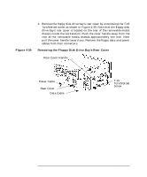 110
110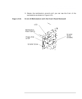 111
111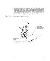 112
112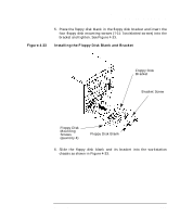 113
113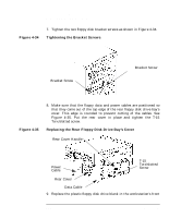 114
114 115
115 116
116 117
117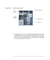 118
118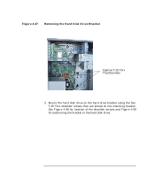 119
119