HP Visualize c3000 hp Visualize b1000 and c3000 workstations owner's guide (a4 - Page 125
Tightening the Bracket Screws, Replacing the CD Drive Bay's Rear Cover
 |
View all HP Visualize c3000 manuals
Add to My Manuals
Save this manual to your list of manuals |
Page 125 highlights
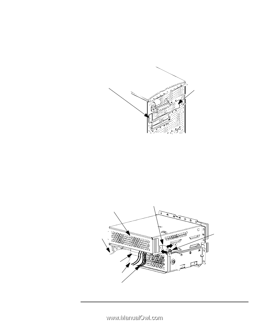
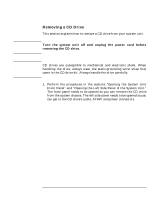
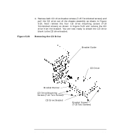
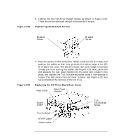
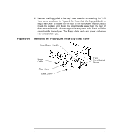
Changing Your Computer Hardware Configuration Removable Media Devices Figure 5-22 6. Tighten the two CD drive bracket screws as shown in Figure 5-22. These should be tightened using 6 inch-pounds of torque. Tightening the Bracket Screws Bracket Screw Bracket Screw Figure 5-23 7. Place the audio, ATAPI and power cables inside the CD drive bay, and position the cables so that they go under the bottom edge of the CD drive bay's rear cover. The CD drive bay's rear cover's edge is rounded to keep you from cutting the cables. See Figure 5-23. Next, place the end opposite the rear cover handle into the cover slot, rotate it into place, and tighten the T-15 Torx/slotted screw using 6 inch-pounds of torque. This will secure the rear cover in place. See Figure 5-23. You have completed the removal of the CD drive. Replacing the CD Drive Bay's Rear Cover Rear Cover Rear Cover Handle Audio Cable Ferrite Bead ATAPI Cable Power Cable T-15 Torx/Slotted Screw Chapter 5 125
-
 1
1 -
2
-
3
-
4
-
5
-
6
-
7
-
8
-
9
-
10
-
11
-
12
-
13
-
14
-
15
-
16
-
17
-
18
-
19
-
20
-
21
-
22
-
23
-
24
-
25
-
26
-
27
-
28
-
29
-
30
-
31
-
32
-
33
-
34
-
35
-
36
-
37
-
38
-
39
-
40
-
41
-
42
-
43
-
44
-
45
-
46
-
47
-
48
-
49
-
50
-
51
-
52
-
53
-
54
-
55
-
56
-
57
-
58
-
59
-
60
-
61
-
62
-
63
-
64
-
65
-
66
-
67
-
68
-
69
-
70
-
71
-
72
-
73
-
74
-
75
-
76
-
77
-
78
-
79
-
80
-
81
-
82
-
83
-
84
-
85
-
86
-
87
-
88
-
89
-
90
-
91
-
92
-
93
-
94
-
95
-
96
-
97
-
98
-
99
-
100
-
101
-
102
-
103
-
104
-
105
-
106
-
107
-
108
-
109
-
110
-
111
-
112
-
113
-
114
-
115
-
116
-
117
-
118
-
119
-
 120
120 -
 121
121 -
 122
122 -
 123
123 -
 124
124 -
 125
125 -
 126
126 -
 127
127 -
 128
128 -
 129
129 -
 130
130 -
131
-
132
-
133
-
134
-
135
-
136
-
137
-
138
-
139
-
140
-
141
-
142
-
143
-
144
-
145
-
146
-
147
-
148
-
149
-
150
-
151
-
152
-
153
-
154
-
155
-
156
-
157
-
158
-
159
-
160
-
161
-
162
-
163
-
164
-
165
-
166
-
167
-
168
-
169
-
170
-
171
-
172
-
173
-
174
-
175
-
176
-
177
-
178
-
179
-
180
-
181
-
182
-
183
-
184
-
185
-
186
-
187
-
188
-
189
-
190
-
191
-
192
-
193
-
194
-
195
-
196
-
197
-
198
-
199
-
200
-
201
-
202
-
203
-
204
-
205
-
206
-
207
-
208
-
209
-
210
-
211
-
212
-
213
-
214
-
215
-
216
-
217
-
218
-
219
-
220
-
221
-
222
-
223
-
224
-
225
-
226
-
227
-
228
-
229
-
230
-
231
-
232
-
233
-
234
-
235
-
236
-
237
-
238
-
239
-
240
-
241
-
242
-
243
-
244
-
245
-
246
 |
 |