HP Xw460c GbE2c Ethernet Blade Switch for HP c-Class Quick Setup Instructions - Page 2
Planning the interconnect switch configuration, Installing the interconnect switch, CAUTION, IMPORTANT
 |
View all HP Xw460c manuals
Add to My Manuals
Save this manual to your list of manuals |
Page 2 highlights
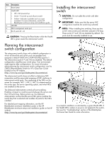
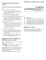
Item Description 1 Reset button 2 Health LED • Off-Not powered up • Green-Powered up and all ports match • Amber-Indicates a problem such as a port mismatch. For more information, see the HP BladeSystem enclosure setup and installation guide. 3 UID LED 4 DB-9 management serial port 5 RJ-45 ports 20 - 24 CAUTION: Pressing the Reset button while the Health LED is green resets the interconnect switch. Installing the interconnect switch CAUTION: Do not cable the switch until after configuration. IMPORTANT: Make sure that the server NIC configuration matches the switch bay selected. NOTE: When installing two switches, there are two switch interconnect ports between adjacent I/O bays. These ports (17 and 18) are disabled by default. The ports must be manually enabled to use. Planning the interconnect switch configuration The interconnect switch ships with a default configuration in which all downlink and uplink ports are enabled and assigned a default VLAN with a VLAN ID (VID) equal to 1. The interconnect ports (17 and 18) are disabled. This default configuration simplifies your initial setup. Your environment might require other configurations. For more information about planning the interconnect switch configuration, see the GbE2c Ethernet Blade Switch for HP c-Class User Guide located on the HP website (http://www.hp.com/go/bladesystem/documentation). The interconnect switch does not affect or determine NIC numeration and the associated mapping of NIC interfaces to interconnect switch ports. The numbering of the NICs on the server (for example, NIC 1, NIC 2, NIC 3) is determined by the server type, the server operating system, and what NICs are enabled on the server. The Onboard Administrator controls all port enabling. Enabling is based on matching ports between the server and the I/O switch bay. Before power up, the Onboard Administrator verifies that the server NIC option matches the switch bay that is selected and enables all ports for the NICs installed. For detailed port mapping information, see the HP BladeSystem enclosure installation poster or the HP BladeSystem enclosure setup and installation guide on the HP website (http://www.hp.com/go/bladesystem/documentation). A successful installation is indicated by a green Health LED. If the Health LED is amber or power is not applied to the switch, then see the "Troubleshooting" section of the BladeSystem Enclosure User Guide for more information.
-
 1
1 -
 2
2 -
 3
3
 |
 |
