HP Xw460c HP BladeSystem c-Class Site Planning Guide - Page 37
Cabinet performance grounding (high frequency ground), Raised floor \, WARNING, IMPORTANT
 |
View all HP Xw460c manuals
Add to My Manuals
Save this manual to your list of manuals |
Page 37 highlights
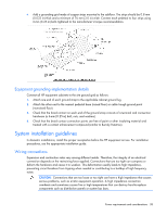
measured above 3.0 V might be hazardous to personnel or cause equipment performance issues and must be corrected before placing the equipment in service. Cabinet performance grounding (high frequency ground) Some safety power distribution wires are too long and too inductive to provide adequate high-frequency return paths. Signal interconnects between system cabinets might need high-frequency ground return paths in addition to the safety or power distribution system 50-60Hz grounding system. HP recommends the use of a properly installed SRG, also bonded to the 50-60Hz grounding system. WARNING: Do not use a cabinet-to-floor ground strap in place of a properly installed safety (50-60Hz) grounding system, nor in place of a properly installed SRG. An improperly installed grounding system can present a shock hazard to personnel. Power panels located in close proximity to the computer equipment should also be connected to the site grounding grid. Raised floor "high-frequency noise" grounding IMPORTANT: Regardless of the grounding connection method used, the raised floor should be grounded as an absolute safety minimum. If a raised floor system is used, the floor must be designed as a signal ground grid that maintains an equal potential over a broad band of frequencies. To accomplish this, observe the following guidelines: • Use a raised floor system where the stringers are bolted to the pedestals. • Select floor components that have a corrosion-resistant plating to provide low resistance connection points to other components and to computer cabinets. • Connect a 2/0 copper conductor to every other pedestal around the perimeter and to the equipment grounding system of the building. • Bond all metal pipes that enter or leave the raised floor area to the 2/0 perimeter ground. • Bond each row and column of the floor grid to the 2/0 perimeter ground. • Bond any I-beams that penetrate the raised floor to the pedestals. • Connect the opposite corners of equipment cabinets to the pedestals with #12 stranded wire. • Where the cabinets are bolted together in rows, bonding two corners at opposite ends of the row is sufficient. • Bonding straps should be 70 cm (24 in) or less in length. If a bolted-stringer raised floor system is not used, the alternate methods that may provide acceptable results include the following: • Use a grounded #6 AWG minimum copper wire grid that is clamped mechanically to floor pedestals and bonded properly to the building or site ground. Power requirements and considerations 37
-
 1
1 -
2
-
3
-
4
-
5
-
6
-
7
-
8
-
9
-
10
-
11
-
12
-
13
-
14
-
15
-
16
-
17
-
18
-
19
-
20
-
21
-
22
-
23
-
24
-
25
-
26
-
27
-
28
-
29
-
30
-
31
-
 32
32 -
 33
33 -
 34
34 -
 35
35 -
 36
36 -
 37
37 -
 38
38 -
 39
39 -
 40
40 -
 41
41 -
 42
42 -
43
-
44
-
45
-
46
-
47
-
48
-
49
-
50
-
51
-
52
-
53
-
54
-
55
-
56
-
57
-
58
-
59
-
60
-
61
-
62
-
63
-
64
-
65
-
66
-
67
-
68
-
69
-
70
-
71
-
72
-
73
 |
 |