HP Xw6600 HP xw and Z Series Workstations - SATA Optical Drive Installation - Page 4
Caution - workstation specifications
 |
UPC - 883585731121
View all HP Xw6600 manuals
Add to My Manuals
Save this manual to your list of manuals |
Page 4 highlights
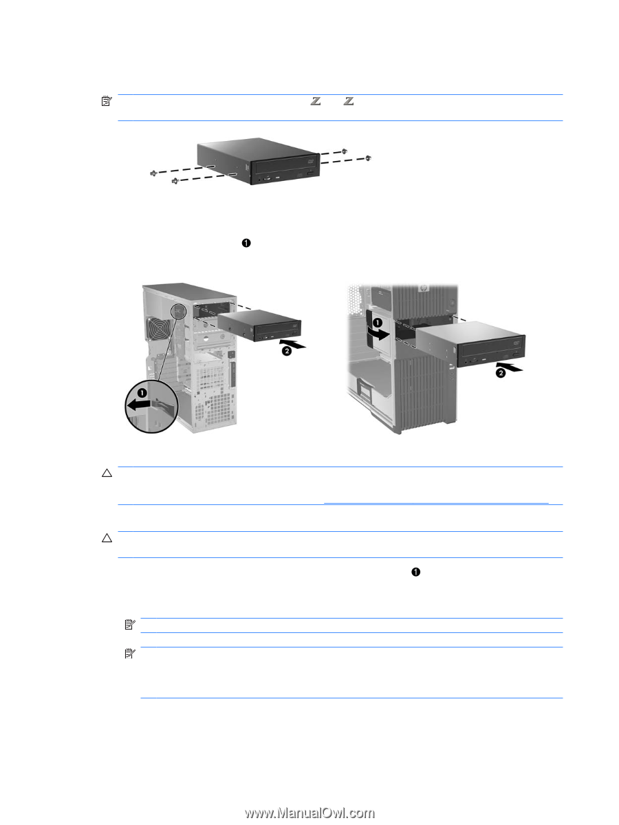
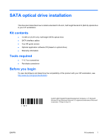
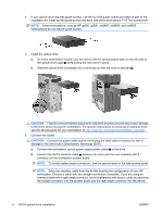
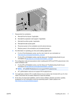
4. If your optical drive requires guide screws, use the four M3 guide screws provided as part of the installation kit. Install two M3 guide screws into each side of the drive using a T-15 Torx screwdriver. NOTE: Some workstations, such as HP 600, 800, xw6600, xw8600, and xw9400 Workstations do not require guide screws. 5. Install the optical drive. a. On some workstation models, you will need to lift the spring-loaded latch on the left side of the optical drive cage while sliding the new drive in place. b. Slide the optical drive completely into a drive bay so that the drive is secured 2. CAUTION: Failure to ensure that the optical drive has been properly secured may cause damage to the drive when moving the workstation. For specific instructions on securing an optional drive, see the service guide for your workstation at http://www.hp.com/support/workstation_manuals. 6. Connect the cables. CAUTION: Connect the power cable before connecting the data cable to reduce the risk of damage to the drive due to Electrostatic Discharge (ESD). a. Connect the workstation optical power supply power cable to the drive. b. Connect the SATA interface cable 2 between the drive and the next available SATA connector on the workstation system board. NOTE: To locate system board connectors, see the service label on the side access panel. NOTE: Select an interface cable from the kit that best fits the configuration of your HP workstation. Choose a cable with two straight connectors if possible. If you are using an interface cable with a right angle connector, avoid interference with plug-in cards by attaching the straight connector into the system board and the right angle connector into the device. 4 SATA optical drive installation ENWW
-
 1
1 -
 2
2 -
 3
3 -
 4
4 -
 5
5 -
 6
6
 |
 |