HP Z600 HP Z Series Workstations - Diskette drive installation - Page 3
Step 1-Preparing for component installation, Step 2-Installing the diskette drive
 |
UPC - 884962074053
View all HP Z600 manuals
Add to My Manuals
Save this manual to your list of manuals |
Page 3 highlights
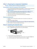
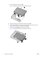
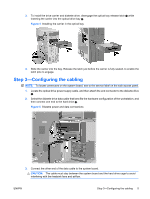
Step 1-Preparing for component installation NOTE: Workstation models vary. All illustrations are examples only. Accessing the internal components of the workstation 1. If you need help preparing the workstation for this installation, consult the removal and replacement procedures in the service guide for your workstation at http://www.hp.com/support/ workstation_manuals. NOTE: For the HP Workstation series, these procedures are also available in the User Guide on the Documentation and Diagnostics CD that shipped with your workstation. 2. Power down the workstation, and then disconnect the power cord. 3. Power down all external devices, and then disconnect them from the workstation. 4. Remove the side access panel. Removing components 1. If present, remove the airflow guide to enable access to the optical bay and system board connectors. 2. Remove the front bezel if applicable. NOTE: The front bezel does not need to be removed on HP 600 and HP 800 Workstations. 3. Remove the filler from the lowest available optical drive bay. Step 2-Installing the diskette drive 1. For HP 400 Workstations, install four black M3 guide screws in the four lower holes on the carrier. Figure 1 Installing guide screws in the carrier for HP 400 Workstations 2. To install the diskette drive in the optical bay carrier: a. Leave the four preinstalled guide screws in the lower holes of the diskette drive in place. b. Use the four guide screws to align the diskette drive with the carrier . ENWW Step 1-Preparing for component installation 3
-
 1
1 -
 2
2 -
 3
3 -
 4
4 -
 5
5 -
 6
6
 |
 |
