| Section |
Page |
| Technical Reference |
1 |
| Technical Reference |
1 |
| Technical Reference |
1 |
| HP B2600 Workstations |
1 |
| Manufacturing Part Number:� n.a. |
1 |
| Edition E0501 |
1 |
| Notice |
2 |
| Notice |
2 |
| Restricted Rights Legend |
2 |
| Restricted Rights Legend |
2 |
| © Copyright 2001 |
2 |
| © Copyright 2001 |
2 |
| Hewlett-Packard Company. All Rights Reserved. This document contains proprietary information that... |
2 |
| © Copyright 1980, 1984 |
2 |
| © Copyright 1980, 1984 |
2 |
| AT&T, Inc. |
2 |
| © Copyright 1979, 1980, 1983 |
2 |
| © Copyright 1979, 1980, 1983 |
2 |
| The Regents of the University of California. This software and documentation is based in part on ... |
2 |
| Preface |
9 |
| Preface |
9 |
| Safety and Regulatory Statements |
9 |
| Safety and Regulatory Statements |
9 |
| Installation Notice |
9 |
| Installation Notice |
9 |
| Related Manuals |
9 |
| Related Manuals |
9 |
| • Installation Poster for the HP B2600 Workstation |
9 |
| • Installation Poster for the HP B2600 Workstation |
9 |
| • Installation Poster for the HP B2600 Workstation |
9 |
| • Getting Started Guide for the HP B2600 Workstation |
9 |
| • Getting Started Guide for the HP B2600 Workstation |
9 |
| • Common Desktop Environment (CDE) User’s Guide |
9 |
| • Common Desktop Environment (CDE) User’s Guide |
9 |
| • Common Desktop Environment (CDE) User’s Guide |
9 |
| • Configuring HP-UX for Peripherals |
9 |
| • Configuring HP-UX for Peripherals |
9 |
| • HP-UX System Administration Tasks |
9 |
| • HP-UX System Administration Tasks |
9 |
| • HP CDE Getting Started Guide |
9 |
| • HP CDE Getting Started Guide |
9 |
| • Managing Systems and Workgroups |
9 |
| • Managing Systems and Workgroups |
9 |
| • Using HP-UX |
9 |
| • Using HP-UX |
9 |
| • Using Your HP Workstation |
9 |
| • Using Your HP Workstation |
9 |
| • Getting Started Guide for the B2600 |
9 |
| • Getting Started Guide for the B2600 |
9 |
| Revision History |
10 |
| Revision History |
10 |
| Edition |
10 |
| Edition |
10 |
| Edition |
10 |
| Revision History |
10 |
| E0501 |
10 |
| E0501 |
10 |
| First Printing |
10 |
| Problems, Questions, and Suggestions |
10 |
| Problems, Questions, and Suggestions |
10 |
| Electrostatic Discharge (ESD) Precautions |
10 |
| Electrostatic Discharge (ESD) Precautions |
10 |
| ESD (electrostatic discharge) |
10 |
| Electrostatic discharge (ESD) |
10 |
| • Work on a static-free mat. |
10 |
| • Work on a static-free mat. |
10 |
| • Wear a static strap to ensure that any accumulated electrostatic charge is discharged from your... |
10 |
| • Create a common ground for the equipment you are working on by connecting the static-free mat, ... |
10 |
| • Keep uninstalled printed circuit boards in their protective antistatic bags. |
10 |
| • Handle printed circuit boards by their edges, once you have removed them from their protective ... |
10 |
| 1� Product Information |
11 |
| 1� Product Information |
11 |
| • Hardware System Overview |
12 |
| • Hardware System Overview |
12 |
| • Operating System Overview |
12 |
| • Your Workstation’s Front Panel |
12 |
| • Your Workstation’s Rear Panel Connectors |
12 |
| • Monitors |
12 |
| • Workstation Characteristics |
12 |
| • Internal Components |
12 |
| Hardware System Overview |
13 |
| Hardware System Overview |
13 |
| Hardware system features |
13 |
| HP B2600 features |
13 |
| <TABLE> |
13 |
| Table�1�1.� HP B2600 Hardware System Features |
13 |
| <TABLE HEADING> |
13 |
| <TABLE ROW> |
13 |
| Workstation Feature |
13 |
| Description |
13 |
| <TABLE BODY> |
13 |
| <TABLE ROW> |
13 |
| Processor |
13 |
| A PA8600 microprocessor with an operating frequency of 500MHz. This processor has a 0.5 MB instru... |
13 |
| <TABLE ROW> |
13 |
| Monitors |
13 |
| PC compatible monitors |
13 |
| <TABLE ROW> |
13 |
| Optional Graphics |
13 |
| Supported graphics devices: |
13 |
| • HP Visualize-fx5 |
13 |
| • HP Visualize-fx5 |
13 |
| • HP Visualize- |
13 |
| <TABLE ROW> |
13 |
| Main Memory |
13 |
| Four memory slots (cards can be mixed): |
13 |
| • 256MB DIMMs |
13 |
| • 256MB DIMMs |
13 |
| • 512MB DIMMs |
13 |
| • 1GB DIMMs |
13 |
| <TABLE ROW> |
13 |
| Internal Storage Devices |
13 |
| Two Low-Voltage Differential (LVD) SCSI hard disk drive and one optional ATAPI CD drive. |
13 |
| <TABLE ROW> |
13 |
| Standard Network |
13 |
| 10/100 Base T LAN connector |
13 |
| <TABLE ROW> |
13 |
| Standard I/O Connectors |
13 |
| Standard workstation I/O ports: |
13 |
| Universal serial bus (USB) |
13 |
| Universal serial bus (USB) |
13 |
| Universal serial bus (USB) |
13 |
| Serial ports 1 and 2 connectors |
13 |
| Serial ports 1 and 2 connectors |
13 |
| • Parallel connector |
13 |
| • LAN connector |
13 |
| <TABLE ROW> |
13 |
| PCI slots |
13 |
| Peripheral component interconnect (PCI) slots |
13 |
| Slot 1: �32 Bit, 5.0V, 33MHz (optional audio card) |
13 |
| <TABLE ROW> |
13 |
| Remote Power-on |
13 |
| Remote power-on |
13 |
| Allows you to turn on your workstation from a remote system. |
13 |
| Operating System Overview |
14 |
| Operating System Overview |
14 |
| Instant ignition |
14 |
| Operating system overview |
14 |
| System overview, operating |
14 |
| Your Workstation’s Front Panel |
15 |
| Your Workstation’s Front Panel |
15 |
| Front panel |
15 |
| Figure�1�1.� System Unit Front Panel |
15 |
| Figure�1�1.� System Unit Front Panel |
15 |
| <GRAPHIC> |
15 |
| System LCD |
15 |
| System LCD |
15 |
| Liquid crystal display (LCD) |
15 |
| LCD symbols |
15 |
| Symbols, LCD |
15 |
| Figure�1�2.� LCD Symbols for System Activities |
15 |
| Figure�1�2.� LCD Symbols for System Activities |
15 |
| <GRAPHIC> |
15 |
| System Power Button |
15 |
| shutdown -q |
15 |
| Power button |
15 |
| Button, power |
15 |
| Your Workstation’s Rear Panel Connectors |
16 |
| Your Workstation’s Rear Panel Connectors |
16 |
| EMI compliance |
16 |
| 10/100 Base T LAN connector |
16 |
| Connector:LAN (10/100 Base T) |
16 |
| Serial ports 1 and 2 connectors |
16 |
| Connector:Serial ports 1 and 2 connectors |
16 |
| Power cord connector |
16 |
| Connector:Power cord |
16 |
| Connector:USB |
16 |
| USB connectors |
16 |
| Parallel connector |
16 |
| • Serial Ports 1 and 2 Connectors |
16 |
| • Serial Ports 1 and 2 Connectors |
16 |
| • USB Connectors |
16 |
| • Power Cord Connector |
16 |
| • Parallel Connector |
16 |
| • Network Connector |
16 |
| NOTE To maintain FCC/EMI compliance, verify that all cables are fully seated and properly fastened. |
16 |
| Rear panel connectors, system unit |
16 |
| System unit rear panel connectors |
16 |
| Rear panel:I/O card slots |
16 |
| Rear panel:Serial ports 1 and 2 connectors |
16 |
| USB connectors |
16 |
| Rear panel:USB connectors |
16 |
| Rear panel:Power input |
16 |
| Power cord connector |
16 |
| Figure 1�3. |
16 |
| Figure�1�3.� System Unit Rear Panel Connectors |
16 |
| Figure�1�3.� System Unit Rear Panel Connectors |
16 |
| <GRAPHIC> |
17 |
| Serial Ports 1 and 2 Connectors |
17 |
| Connector:Serial ports 1 and 2 connectors |
17 |
| Serial ports 1 and 2 connectors |
17 |
| USB Connectors |
17 |
| USB Connectors |
17 |
| Connector:USB |
17 |
| USB connectors |
17 |
| Keyboard |
17 |
| Keyboard |
17 |
| USB:Keyboard |
17 |
| Keyboard, USB |
17 |
| HP Mouse |
17 |
| HP Mouse |
17 |
| Mouse, HP |
17 |
| HP mouse, USB |
17 |
| USB:HP mouse |
17 |
| Power Cord Connector |
18 |
| Power Cord Connector |
18 |
| Connector:Power cord |
18 |
| Parallel Connector |
18 |
| Parallel Connector |
18 |
| Network Connector |
18 |
| Network Connector |
18 |
| Connector:10/100 Base T LAN |
18 |
| Network connector |
18 |
| 10/100 Base T LAN connector |
18 |
| Audio Connectors (optional) |
18 |
| Audio Connectors (optional) |
18 |
| Monitors |
19 |
| Monitors |
19 |
| Monitors |
19 |
| Workstation Conversion Process |
20 |
| Workstation Conversion Process |
20 |
| Desktop to Rack-Mount Conversion |
20 |
| Desktop to Rack-Mount Conversion |
20 |
| Rack-Mount to Desktop Conversion |
20 |
| Rack-Mount to Desktop Conversion |
20 |
| Workstation Characteristics |
21 |
| Workstation Characteristics |
21 |
| <TABLE> |
21 |
| Table�1�2.� Workstation Characteristics |
21 |
| <TABLE HEADING> |
21 |
| <TABLE ROW> |
21 |
| Characteristic |
21 |
| Description |
21 |
| <TABLE BODY> |
21 |
| <TABLE ROW> |
21 |
| Weight Rack System (excl. keyboard and display) Weight Desk-side System (excl. keyboard and display) |
21 |
| 14.1 kg (31.0 lb.) 15.9 kg (35.0 lb.) |
21 |
| <TABLE ROW> |
21 |
| Dimensions Rack System |
21 |
| Depth: 45.77 cm (18.02 inches) Width: 42.50 cm (16.73 inches) Height: 12.70 cm (5.00 inches) |
21 |
| <TABLE ROW> |
21 |
| Dimensions Desk-side System |
21 |
| Depth: 47.02 cm (18.51 inches) Width: 43.26 cm (17.03 inches) Height: 13.67 cm (5.38 inches) |
21 |
| <TABLE ROW> |
21 |
| Storage temperature |
21 |
| -40�C to +70�C (-40�F to +158�F) |
21 |
| <TABLE ROW> |
21 |
| Storage humidity |
21 |
| 8% to 90% (relative) |
21 |
| <TABLE ROW> |
21 |
| Operating temperature |
21 |
| +5�C to +35�C (+41�F to +95�F) |
21 |
| <TABLE ROW> |
21 |
| Operating humidity |
21 |
| 15% to 80% (relative) |
21 |
| <TABLE ROW> |
21 |
| Input Current |
21 |
| 3.6 – 3.0 amps (AC at 100 to 120 Vac) 1.8 – 1.5 amps (AC at 200 to 240 Vac) |
21 |
| <TABLE ROW> |
21 |
| Input Frequency |
21 |
| 50Hz/60Hz |
21 |
| <TABLE ROW> |
21 |
| Sound Power Rack System |
21 |
| 5.5 Bels LwA max. at 30�C (88�F) |
21 |
| <TABLE ROW> |
21 |
| Sound Power Desk-side System |
21 |
| 5.0 Bels LwA max. at 30�C (88�F) |
21 |
| Internal Components |
22 |
| Internal Components |
22 |
| Figure�1�4.� Internal Components of the B2600 |
22 |
| Figure�1�4.� Internal Components of the B2600 |
22 |
| <GRAPHIC> |
23 |
| 2� Troubleshooting |
25 |
| 2� Troubleshooting |
25 |
| Chapter Overview |
26 |
| Chapter Overview |
26 |
| Introduction to Troubleshooting |
26 |
| Introduction to Troubleshooting |
26 |
| Flowcharts for Troubleshooting |
26 |
| Flowcharts for Troubleshooting |
26 |
| WARNING Before removing any FRU, PCI card, DIMM or power supply connectors, you must disconnect t... |
26 |
| Figure�2�1.� Main Flowchart for Troubleshooting |
27 |
| Figure�2�1.� Main Flowchart for Troubleshooting |
27 |
| <GRAPHIC> |
28 |
| Figure�2�2.� Console Troubleshooting Flowchart |
28 |
| <GRAPHIC> |
29 |
| Figure�2�3.� Bootable Device Troubleshooting Flowchart |
29 |
| <GRAPHIC> |
30 |
| Figure�2�4.� HP-UX Troubleshooting Flowchart |
30 |
| <GRAPHIC> |
31 |
| Identifying LCD-Indicated Conditions |
31 |
| XXX YYYY: ZZZZZZ����������������(Line 1) |
31 |
| XXX YYYY: ZZZZZZ����������������(Line 1) |
31 |
| AAAAAAAAAAAAAAAA����������������(Line 2) |
31 |
| <TABLE> |
31 |
| <TABLE BODY> |
31 |
| <TABLE ROW> |
31 |
| XXX |
31 |
| XXX |
31 |
| Three-character Operating Status |
31 |
| <TABLE ROW> |
31 |
| YYYY |
31 |
| YYYY |
31 |
| Four-digit hex code identifying the code module being executed |
31 |
| <TABLE ROW> |
31 |
| ZZZZZZ |
31 |
| ZZZZZZ |
31 |
| Six-digit FRU descriptor |
31 |
| <TABLE ROW> |
31 |
| AAAAAAAAAAAAAAAA |
31 |
| AAAAAAAAAAAAAAAA |
31 |
| Diagnostic message of up to 16 characters |
31 |
| <TABLE> |
31 |
| <TABLE BODY> |
31 |
| <TABLE ROW> |
31 |
| FLT (fault) |
31 |
| FLT |
31 |
| A hardware error has been detected |
31 |
| <TABLE ROW> |
31 |
| TST (test) |
31 |
| TST |
31 |
| Hardware being tested |
31 |
| <TABLE ROW> |
31 |
| INI (initialize) |
31 |
| INI |
31 |
| Hardware being initialized |
31 |
| <TABLE ROW> |
31 |
| SHU (shutdown) |
31 |
| SHU |
31 |
| System being shutdown |
31 |
| <TABLE ROW> |
31 |
| WRN (warning) |
31 |
| WRN |
31 |
| A non-optimal operating condition exists |
31 |
| <TABLE ROW> |
31 |
| RUN (running) |
31 |
| RUN |
31 |
| The operating system is running |
31 |
| Selftest Failures |
31 |
| Selftest Failures |
31 |
| 1. In Table C-1 of the “HP B2600 Chassis Codes” appendix, find the chassis code listed on the LCD. |
31 |
| 1. In Table C-1 of the “HP B2600 Chassis Codes” appendix, find the chassis code listed on the LCD. |
31 |
| 2. In the Boot Console Handler, use the Service Menu’s |
31 |
| Memory Failures |
32 |
| Memory Failures |
32 |
| Running System Verification Tests |
33 |
| Running System Verification Tests |
33 |
| man cstm [Enter] |
33 |
| man cstm [Enter] |
33 |
| man cstm [Enter] |
33 |
| man mstm [Enter] |
33 |
| man mstm [Enter] |
33 |
| man xstm [Enter] |
33 |
| man xstm [Enter] |
33 |
| 1. In a terminal window, type the following at the # prompt to invoke the command line interface:... |
33 |
| 1. In a terminal window, type the following at the # prompt to invoke the command line interface:... |
33 |
| 2. The following message appears: |
33 |
| 3. To verify the system operation, type the following at the |
33 |
| 4. Press |
33 |
| 5. To exit the Support Tools Manager, enter the following: |
33 |
| Tests:ODE-based diagnostics |
34 |
| Tests:ODE-based diagnostics |
34 |
| Tests:ODE-based diagnostics |
34 |
| Troubleshooting:ODE-based diagnostics |
34 |
| J5000/J7000 workstation:ODE-based diagnostics |
34 |
| ODE-based diagnostics |
34 |
| Diagnostics, ODE-based |
34 |
| Running:ODE-based diagnostics |
34 |
| 1. Invoke the ISL environment from the system disk or a CD ROM. |
34 |
| 1. Invoke the ISL environment from the system disk or a CD ROM. |
34 |
| 2. Type |
34 |
| • astrodiag |
34 |
| • astrodiag |
34 |
| • astrodiag |
34 |
| • siodiag |
34 |
| • siodiag |
34 |
| • wdiag |
34 |
| • wdiag |
34 |
| • memtest |
34 |
| • memtest |
34 |
| • fupdate – updates the system’s Processor Dependent Code (PDC) firmware in the FEPROM or Flash ROM. |
34 |
| • mapper |
34 |
| • mapper |
34 |
| 3� Remove/Replace System Components |
35 |
| 3� Remove/Replace System Components |
35 |
| Chapter Overview |
36 |
| Chapter Overview |
36 |
| • Tools Required — a list of tools necessary for removing and replacing system components. |
36 |
| • Tools Required — a list of tools necessary for removing and replacing system components. |
36 |
| • Removing/Replacing System Components — a set of procedures for removing/replacing: front bezel,... |
36 |
| WARNING For most of the installation and removal procedures in this chapter, you must power off t... |
36 |
| NOTE To maintain FCC/EMI compliance, verify that all covers are replaced and that all screws are ... |
36 |
| Workstation Configurations |
36 |
| Workstation Configurations |
36 |
| http://www.hp.com/workstations |
36 |
| Tools Required |
37 |
| Tools Required |
37 |
| • Light-duty flat blade screwdriver with 6-inch (150 mm) blade |
37 |
| • Light-duty flat blade screwdriver with 6-inch (150 mm) blade |
37 |
| • Number 2 Phillips screwdriver with 6-inch (150mm) blade |
37 |
| • T-10 and T-15 Torx driver |
37 |
| • ESD equipment (see the “Electrostatic Discharge (ESD) Precautions” section later in this chapte... |
37 |
| Removing/Replacing System Components |
38 |
| Removing/Replacing System Components |
38 |
| NOTE If you need to install a new system component, simply follow the procedures for |
38 |
| Electrostatic Discharge (ESD) Precautions |
38 |
| Electrostatic Discharge (ESD) Precautions |
38 |
| • Work on a static-free mat. |
38 |
| • Work on a static-free mat. |
38 |
| • Wear a static strap to ensure that any accumulated electrostatic charge is discharged from your... |
38 |
| • Create a common ground for the equipment you are working on by connecting the static-free mat, ... |
38 |
| • Keep uninstalled printed circuit boards in their protective antistatic bags. |
38 |
| • Handle printed circuit boards by their edges, once you have removed them from their protective ... |
38 |
| Prerequisite for Using the Procedures in this Chapter |
39 |
| Prerequisite for Using the Procedures in this Chapter |
39 |
| 1. Power off the workstation (either by executing |
39 |
| 1. Power off the workstation (either by executing |
39 |
| 2. Unplug the workstation power cord and all peripheral devices from AC power outlets. If you are... |
39 |
| 3. Attach the static-grounding wrist strap by following the instructions on the package. Attach t... |
39 |
| NOTE To make access to the internal components easier, you may want to place the workstation on a... |
39 |
| CAUTION This workstation is designated for two-person lifting; it weighs approximately 35.0 pound... |
39 |
| Removing the Front Bezel and Top Cover |
40 |
| Removing the Front Bezel and Top Cover |
40 |
| Removing the Front Bezel and Top Cover |
40 |
| Removing the Front Bezel and Top Cover |
40 |
| 1. Turn your workstation off and unplug it. |
40 |
| 1. Turn your workstation off and unplug it. |
40 |
| 2. Lay your workstation on a soft anti-static surface with the HP logo text in the upright position. |
40 |
| 3. Press in on both release buttons found on the ends of the bezel and pull outward from the work... |
40 |
| Figure�3�1.� Front Bezel and Top Cover Removal |
40 |
| Figure�3�1.� Front Bezel and Top Cover Removal |
40 |
| <GRAPHIC> |
41 |
| Replacing the Front Bezel and Top Cover |
41 |
| Replacing the Front Bezel and Top Cover |
41 |
| Replacing the Front Bezel and Top Cover |
41 |
| 1. Slide the top cover back on the workstation and secure it by screwing in the captive screws. |
41 |
| 1. Slide the top cover back on the workstation and secure it by screwing in the captive screws. |
41 |
| 2. Next, push the bezel in place on the front of the workstation. See |
41 |
| Figure�3�2.� Front Bezel and Top Cover Replacement |
41 |
| Figure�3�2.� Front Bezel and Top Cover Replacement |
41 |
| <GRAPHIC> |
42 |
| Removing Memory DIMMs |
42 |
| 1. Complete the procedure in the section |
42 |
| 1. Complete the procedure in the section |
42 |
| 2. Press downward on the tabs that are located on both ends of the memory card slots. See |
42 |
| Figure�3�3.� Pressing Down on the Memory Slot Tabs |
42 |
| Figure�3�3.� Pressing Down on the Memory Slot Tabs |
42 |
| <GRAPHIC> |
42 |
| Figure�3�4.� Lifting a DIMM Card Out of the Memory Slot |
42 |
| Figure�3�4.� Lifting a DIMM Card Out of the Memory Slot |
42 |
| <GRAPHIC> |
43 |
| Memory Configuration |
43 |
| Figure�3�5.� Memory Loading Sequence in the HP B2600 |
43 |
| Figure�3�5.� Memory Loading Sequence in the HP B2600 |
43 |
| <GRAPHIC> |
44 |
| Replacing Memory DIMMs |
44 |
| 1. Remove the current DIMM(s) if you have not already done this. Otherwise, skip this step. To re... |
44 |
| 1. Remove the current DIMM(s) if you have not already done this. Otherwise, skip this step. To re... |
44 |
| 2. Determine the appropriate memory slot(s) for your DIMM card(s). See |
44 |
| Figure�3�6.� Memory Loading Sequence in the HP B2600 |
44 |
| Figure�3�6.� Memory Loading Sequence in the HP B2600 |
44 |
| <GRAPHIC> |
45 |
| Figure�3�7.� Inserting the DIMM Card into a Memory Slot |
45 |
| Figure�3�7.� Inserting the DIMM Card into a Memory Slot |
45 |
| <GRAPHIC> |
45 |
| 5. Connect and turn on the power to your system. |
45 |
| 6. Determine that your memory installation was successful by executing the |
45 |
| Removing the CD Drive |
46 |
| Removing the CD Drive |
46 |
| 1. Complete the procedure in the section |
46 |
| 1. Complete the procedure in the section |
46 |
| 2. Disconnect the CD drive control cable by pulling up on its pull tab and disconnect the power c... |
46 |
| Figure�3�8.� Disconnecting the CD Drive Control Cable |
46 |
| Figure�3�8.� Disconnecting the CD Drive Control Cable |
46 |
| <GRAPHIC> |
46 |
| 4. Press in on the retainer clips on both sides of the CD drive bay and pull toward you. See |
47 |
| 5. Take the back cover off the CD drive bay by lifting up on the raised portion of the back cover... |
47 |
| Figure�3�11.� Removing the CD Drive Bay’s Back Cover |
47 |
| Figure�3�11.� Removing the CD Drive Bay’s Back Cover |
47 |
| <GRAPHIC> |
48 |
| 7. Unscrew the four CD drive mounting screws located on both sides of the CD drive bay. See |
48 |
| Figure�3�13.� Unscrew the Four CD Drive Mounting Screws |
48 |
| Figure�3�13.� Unscrew the Four CD Drive Mounting Screws |
48 |
| <GRAPHIC> |
49 |
| Replacing the CD Drive |
50 |
| Replacing the CD Drive |
50 |
| 1. Remove the current CD drive if you have not already done this. Otherwise, skip this step. To r... |
50 |
| 1. Remove the current CD drive if you have not already done this. Otherwise, skip this step. To r... |
50 |
| 2. Slide the CD drive into the CD drive bay. See |
50 |
| 3. Screw the four CD drive mounting screws into their threaded holes located on both sides of the... |
50 |
| Figure�3�16.� Screw in the Four CD Drive Mounting Screws |
50 |
| Figure�3�16.� Screw in the Four CD Drive Mounting Screws |
50 |
| <GRAPHIC> |
51 |
| 5. Replace the back cover on the CD drive bay by inserting the hinge tabs located on the CD drive... |
51 |
| 6. Slide the CD drive bay and CD drive back into the workstation. You will hear the retainer clip... |
52 |
| 7. Connect the CD drive power cable by pushing it into its connector on the system board and conn... |
52 |
| Figure�3�20.� Connecting the CD Drive Power and Control Cables |
52 |
| Figure�3�20.� Connecting the CD Drive Power and Control Cables |
52 |
| <GRAPHIC> |
53 |
| 9. Complete the procedure in the section |
53 |
| 10. Connect and turn on the power to your system. |
53 |
| 11. Determine that your CD drive replacement was successful by executing the |
53 |
| Removing the PCI Cage, I/O Card and PCI Backplane Board |
54 |
| Removing the PCI Cage, I/O Card and PCI Backplane Board |
54 |
| PCI Cage Removal |
54 |
| PCI Cage Removal |
54 |
| 1. Complete the procedure in the section |
54 |
| 1. Complete the procedure in the section |
54 |
| 2. Complete the procedure in the section |
54 |
| 3. Lift up on the PCI cage handle ( |
54 |
| Figure�3�22.� Lifting Up on the PCI Cage Handle |
54 |
| Figure�3�22.� Lifting Up on the PCI Cage Handle |
54 |
| <GRAPHIC> |
54 |
| Figure�3�23.� Removing the PCI Cage from the System |
54 |
| Figure�3�23.� Removing the PCI Cage from the System |
54 |
| <GRAPHIC> |
55 |
| I/O Card Removal |
55 |
| 1. Set the PCI cage on an anti-static surface and remove the PCI cage cover. See |
55 |
| 1. Set the PCI cage on an anti-static surface and remove the PCI cage cover. See |
55 |
| Figure�3�24.� Removing the PCI Cage Cover |
55 |
| Figure�3�24.� Removing the PCI Cage Cover |
55 |
| <GRAPHIC> |
55 |
| Figure�3�25.� Unscrewing the I/O Card’s Bulkhead Screw |
55 |
| Figure�3�25.� Unscrewing the I/O Card’s Bulkhead Screw |
55 |
| <GRAPHIC> |
56 |
| Figure�3�26.� Removing the I/O Card from Its PCI Slot |
56 |
| Figure�3�26.� Removing the I/O Card from Its PCI Slot |
56 |
| <GRAPHIC> |
56 |
| PCI Backplane Board Removal |
56 |
| PCI Backplane Board Removal |
56 |
| 1. Unscrew the three T-15 Torx screws. See |
56 |
| 1. Unscrew the three T-15 Torx screws. See |
56 |
| Figure�3�27.� Unscrew the PCI Backplane’s Three T-15 Torx Screws |
56 |
| Figure�3�27.� Unscrew the PCI Backplane’s Three T-15 Torx Screws |
56 |
| <GRAPHIC> |
57 |
| Figure�3�28.� Removing the PCI Backplane Board |
57 |
| Figure�3�28.� Removing the PCI Backplane Board |
57 |
| <GRAPHIC> |
58 |
| PCI Card Guide Removal |
58 |
| 1. Push the card guide forward with your thumb in the direction of the large arrow and at the sam... |
58 |
| 1. Push the card guide forward with your thumb in the direction of the large arrow and at the sam... |
58 |
| Figure�3�29.� Pushing the Card Guide Forward and Down |
58 |
| Figure�3�29.� Pushing the Card Guide Forward and Down |
58 |
| <GRAPHIC> |
58 |
| Figure�3�30.� Removing the Card Guide from the PCI Cover |
58 |
| Figure�3�30.� Removing the Card Guide from the PCI Cover |
58 |
| <GRAPHIC> |
59 |
| Replacing the PCI Cage, I/O Card and PCI Backplane Board |
59 |
| PCI Backplane Board Replacement |
59 |
| PCI Backplane Board Replacement |
59 |
| 1. Remove the current CD drive, DAT drive or flexible disk drive if you have not already done thi... |
59 |
| 1. Remove the current CD drive, DAT drive or flexible disk drive if you have not already done thi... |
59 |
| 2. Slide the PCI backplane board onto the PCI cage’s standoffs. See |
59 |
| Figure�3�31.� Replacing the PCI Backplane Board |
59 |
| Figure�3�31.� Replacing the PCI Backplane Board |
59 |
| <GRAPHIC> |
59 |
| Figure�3�32.� Screw in the PCI Backplane Board’s Three Screws |
59 |
| Figure�3�32.� Screw in the PCI Backplane Board’s Three Screws |
59 |
| <GRAPHIC> |
60 |
| I/O Card Replacement |
60 |
| 1. Replace the PCI backplane board in the PCI cage if you have not already done this. Otherwise, ... |
60 |
| 1. Replace the PCI backplane board in the PCI cage if you have not already done this. Otherwise, ... |
60 |
| 2. Remove the I/O card from its anti-static bag, which protects it from any possible electro-stat... |
60 |
| 3. Grasp the I/O card’s bulkhead and the back edge and insert it into its PCI slot. See |
60 |
| Figure�3�33.� Inserting the I/O Card into its PCI Slot |
60 |
| Figure�3�33.� Inserting the I/O Card into its PCI Slot |
60 |
| <GRAPHIC> |
60 |
| Figure�3�34.� Screwing in the I/O Card’s Bulkhead Screw |
60 |
| Figure�3�34.� Screwing in the I/O Card’s Bulkhead Screw |
60 |
| <GRAPHIC> |
61 |
| Figure�3�35.� Replacing the PCI Cage Cover |
61 |
| Figure�3�35.� Replacing the PCI Cage Cover |
61 |
| <GRAPHIC> |
61 |
| PCI Cage Replacement |
61 |
| 1. Replace the I/O card(s) in the PCI cage if you have not already done this. Otherwise, skip thi... |
61 |
| 1. Replace the I/O card(s) in the PCI cage if you have not already done this. Otherwise, skip thi... |
61 |
| 2. Push down on the PCI cage handle and on the back of the PCI cage. Next, rotate the PCI cage ha... |
61 |
| Figure�3�36.� Placing the PCI Cage into the Workstation |
61 |
| Figure�3�36.� Placing the PCI Cage into the Workstation |
61 |
| <GRAPHIC> |
61 |
| 4. Complete the procedure in the section |
61 |
| 5. Connect and turn on the power to your system. |
61 |
| 6. Determine that your I/O cards were replaced successfully by executing this command as |
62 |
| PCI Card Guide Replacement |
62 |
| PCI Card Guide Replacement |
62 |
| 1. Locate the front of the card guide slot and the card guide lip. See |
62 |
| 1. Locate the front of the card guide slot and the card guide lip. See |
62 |
| Figure�3�37.� Pushing the Card Guide Forward and Down |
62 |
| Figure�3�37.� Pushing the Card Guide Forward and Down |
62 |
| <GRAPHIC> |
62 |
| Figure�3�38.� Replacing the Card Guide into the PCI Cage Cover |
62 |
| Figure�3�38.� Replacing the Card Guide into the PCI Cage Cover |
62 |
| <GRAPHIC> |
63 |
| Removing the Hard Disk Drive(s) |
63 |
| 1. Complete the procedure in the section |
63 |
| 1. Complete the procedure in the section |
63 |
| 2. Complete the procedure in the section |
63 |
| 3. Grasp the hard disk drive handle and pull it back, then lift up on the handle. See |
63 |
| Figure�3�39.� Removing the Hard Disk Drive and Its Mounting Bracket |
63 |
| Figure�3�39.� Removing the Hard Disk Drive and Its Mounting Bracket |
63 |
| <GRAPHIC> |
63 |
| Figure�3�40.� Removing the Hard Disk Drive from the Hard Disk Drive Bracket |
63 |
| Figure�3�40.� Removing the Hard Disk Drive from the Hard Disk Drive Bracket |
63 |
| <GRAPHIC> |
64 |
| Replacing the Hard Disk Drive(s) |
64 |
| 1. Remove the CD drive, DAT drive or flexible disk drive if you have not already done this. Other... |
64 |
| 1. Remove the CD drive, DAT drive or flexible disk drive if you have not already done this. Other... |
64 |
| 2. Remove the PCI cage if you have not already done this. Otherwise, skip this step. To remove th... |
64 |
| 3. Insert the hard disk drive into the hard disk drive bracket and align the holes in the disk dr... |
64 |
| Figure�3�41.� Installing the Hard Disk Drive into the Hard Disk Drive Bracket |
64 |
| Figure�3�41.� Installing the Hard Disk Drive into the Hard Disk Drive Bracket |
64 |
| <GRAPHIC> |
64 |
| Figure�3�42.� Replacing the Hard Disk Drive and Bracket in the Workstation |
64 |
| Figure�3�42.� Replacing the Hard Disk Drive and Bracket in the Workstation |
64 |
| <GRAPHIC> |
65 |
| 6. Complete the procedure in the section |
65 |
| 7. Complete the procedure in the section |
65 |
| 8. Connect and turn on the power to your system. |
65 |
| 9. Determine that your hard disk drive replacement was successful by executing the |
65 |
| Removing the Liquid Crystal Display (LCD) Module |
66 |
| Removing the Liquid Crystal Display (LCD) Module |
66 |
| 1. Complete the procedure in the section |
66 |
| 1. Complete the procedure in the section |
66 |
| 2. Disconnect the LCD control cable. See |
66 |
| Figure�3�43.� Disconnecting the LCD Control Cable |
66 |
| Figure�3�43.� Disconnecting the LCD Control Cable |
66 |
| <GRAPHIC> |
66 |
| Figure�3�44.� Removing the LCD Module |
66 |
| Figure�3�44.� Removing the LCD Module |
66 |
| <GRAPHIC> |
67 |
| Replacing the Liquid Crystal Display (LCD) Module |
67 |
| 1. Remove the front bezel if you have not already done this. Otherwise, skip this step. To remove... |
67 |
| 1. Remove the front bezel if you have not already done this. Otherwise, skip this step. To remove... |
67 |
| 2. Replace the LCD Module by inserting the left-side and right-side retainer clips in their slots... |
67 |
| Figure�3�45.� Replacing the LCD Module |
67 |
| Figure�3�45.� Replacing the LCD Module |
67 |
| <GRAPHIC> |
67 |
| Figure�3�46.� Connection the LCD Control Cable Connector |
67 |
| Figure�3�46.� Connection the LCD Control Cable Connector |
67 |
| <GRAPHIC> |
67 |
| 5. Connect and turn on the power to your system. |
67 |
| 6. Determine that your LCD Module replacement was successful by looking at the LCD and noticing i... |
67 |
| Removing the AC or DC Power Supply |
68 |
| Removing the AC or DC Power Supply |
68 |
| 1. Unplug the power cord from the system as stated in the WARNING at the beginning of this chapter. |
68 |
| 1. Unplug the power cord from the system as stated in the WARNING at the beginning of this chapter. |
68 |
| 2. Complete the procedure in the section |
68 |
| 3. Disconnect the power supply cables from the system board by pressing in on the latch releases ... |
68 |
| Figure�3�47.� Disconnect the Power Supply Cables |
68 |
| Figure�3�47.� Disconnect the Power Supply Cables |
68 |
| <GRAPHIC> |
69 |
| Figure�3�48.� Unscrewing the Four Power Supply Mounting Screws |
69 |
| Figure�3�48.� Unscrewing the Four Power Supply Mounting Screws |
69 |
| <GRAPHIC> |
69 |
| Figure�3�49.� Removing the AC Power Supply |
69 |
| Figure�3�49.� Removing the AC Power Supply |
69 |
| <GRAPHIC> |
70 |
| Replacing the AC or DC Power Supply |
70 |
| 1. Remove the AC power supply if you have not already done this. Otherwise, skip this step. To re... |
70 |
| 1. Remove the AC power supply if you have not already done this. Otherwise, skip this step. To re... |
70 |
| 2. Replace the AC power supply in the workstation. To do this, you will have to slide the power s... |
70 |
| Figure�3�50.� Replacing the AC Power Supply |
70 |
| Figure�3�50.� Replacing the AC Power Supply |
70 |
| <GRAPHIC> |
70 |
| Figure�3�51.� Screwing in the Four Power Supply Mounting Screws |
70 |
| Figure�3�51.� Screwing in the Four Power Supply Mounting Screws |
70 |
| <GRAPHIC> |
71 |
| Figure�3�52.� Connect the Power Supply Cables |
71 |
| Figure�3�52.� Connect the Power Supply Cables |
71 |
| <GRAPHIC> |
71 |
| 6. Connect and turn on the power to your system. |
71 |
| 7. Determine that your AC power supply replacement was successful by observing to see if the work... |
71 |
| Removing the System Board |
72 |
| Removing the System Board |
72 |
| 1. Complete the procedure in the section |
72 |
| 1. Complete the procedure in the section |
72 |
| 2. Complete the procedure in the section |
72 |
| 3. Complete the procedure in the section |
72 |
| 4. Complete the procedure in the section |
72 |
| 5. Disconnect the two fan power connectors from the system board by pressing in on the latch reta... |
72 |
| Figure�3�53.� Removing the Internal System Board Mounting Screws |
72 |
| Figure�3�53.� Removing the Internal System Board Mounting Screws |
72 |
| <GRAPHIC> |
72 |
| Figure�3�54.� Removing the System Boards Rear Mounting Screw |
72 |
| Figure�3�54.� Removing the System Boards Rear Mounting Screw |
72 |
| <GRAPHIC> |
73 |
| Figure�3�55.� Slide the System Board Off Its Standoffs |
73 |
| Figure�3�55.� Slide the System Board Off Its Standoffs |
73 |
| <GRAPHIC> |
73 |
| Figure�3�56.� Lifting the System Board Out of the Workstation |
73 |
| Figure�3�56.� Lifting the System Board Out of the Workstation |
73 |
| <GRAPHIC> |
74 |
| Replacing the System Board |
74 |
| 1. Remove the system board if you have not already done this. Otherwise, skip this step. To remov... |
74 |
| 1. Remove the system board if you have not already done this. Otherwise, skip this step. To remov... |
74 |
| 2. Use the system board’s turbo-cooler heatsink and handle to place it in the workstation. The sy... |
74 |
| Figure�3�57.� Placing the System Board in the Workstation |
74 |
| Figure�3�57.� Placing the System Board in the Workstation |
74 |
| <GRAPHIC> |
74 |
| Figure�3�58.� Sliding the System Board Onto Its Standoffs |
74 |
| Figure�3�58.� Sliding the System Board Onto Its Standoffs |
74 |
| <GRAPHIC> |
75 |
| Figure�3�59.� Screwing in the System Board’s Rear Mounting Screw |
75 |
| Figure�3�59.� Screwing in the System Board’s Rear Mounting Screw |
75 |
| <GRAPHIC> |
75 |
| Figure�3�60.� Replacing the Internal System Board Mounting Screws |
75 |
| Figure�3�60.� Replacing the Internal System Board Mounting Screws |
75 |
| <GRAPHIC> |
75 |
| 7. Complete the procedure in the section |
75 |
| 8. Complete the procedure in the section |
75 |
| 9. Complete the procedure in the section |
75 |
| 10. Complete the procedure in the section |
76 |
| 11. Connect and turn on the power to your system. |
76 |
| 12. Determine that your system board replacement was successful by observing to see if the workst... |
76 |
| Removing the Fan Modules |
77 |
| Removing the Fan Modules |
77 |
| <TABLE> |
77 |
| Table�3�1.� System Area and PCI area Fan Numbers |
77 |
| <TABLE HEADING> |
77 |
| <TABLE ROW> |
77 |
| Fan Number |
77 |
| Description |
77 |
| <TABLE BODY> |
77 |
| <TABLE ROW> |
77 |
| 1 |
77 |
| Power Supply Fan |
77 |
| <TABLE ROW> |
77 |
| 2 |
77 |
| Right System Area Fan (as you face the system’s front) |
77 |
| <TABLE ROW> |
77 |
| 3 |
77 |
| Left System Area Fan (as you face the system’s front) |
77 |
| <TABLE ROW> |
77 |
| 5 |
77 |
| Left PCI Area Fan (as you face the system’s front) |
77 |
| <TABLE ROW> |
77 |
| 6 |
77 |
| Right PCI Area Fan (as you face the system’s front) |
77 |
| <TABLE ROW> |
77 |
| 7 |
77 |
| CPU’s Turbo-Cooler Heatsink |
77 |
| Figure�3�61.� System and PCI Fan Areas |
77 |
| Figure�3�61.� System and PCI Fan Areas |
77 |
| <GRAPHIC> |
78 |
| System Area Fan Module Removal |
78 |
| 1. Complete the procedure in the section |
78 |
| 1. Complete the procedure in the section |
78 |
| 2. Complete the procedure in the section |
78 |
| 3. Unscrew the two LCD connector screws and remove the LCD connector from its opening in the chas... |
78 |
| Figure�3�62.� Removing the LCD Connector |
78 |
| Figure�3�62.� Removing the LCD Connector |
78 |
| <GRAPHIC> |
78 |
| Figure�3�63.� Disconnecting the Fan-Module Power Cables for the System Area |
78 |
| Figure�3�63.� Disconnecting the Fan-Module Power Cables for the System Area |
78 |
| <GRAPHIC> |
79 |
| Figure�3�64.� Removing the Fan-Module Mounting Screw |
79 |
| Figure�3�64.� Removing the Fan-Module Mounting Screw |
79 |
| <GRAPHIC> |
79 |
| Figure�3�65.� Removing the System Area Fan Module |
79 |
| Figure�3�65.� Removing the System Area Fan Module |
79 |
| <GRAPHIC> |
80 |
| PCI Area Fan Module Removal |
80 |
| 1. Complete the procedure in the section |
80 |
| 1. Complete the procedure in the section |
80 |
| 2. Complete the procedure in the section |
80 |
| 3. Disconnect the two fan-module power cables from the system board by pressing in on the latch r... |
80 |
| Figure�3�66.� Disconnecting the Fan-Module Power Cables |
80 |
| Figure�3�66.� Disconnecting the Fan-Module Power Cables |
80 |
| <GRAPHIC> |
80 |
| Figure�3�67.� Remove the Fan-Module Mounting Screw for the PCI Area |
80 |
| Figure�3�67.� Remove the Fan-Module Mounting Screw for the PCI Area |
80 |
| <GRAPHIC> |
81 |
| Figure�3�68.� Removing the PCI Area Fan Module |
81 |
| Figure�3�68.� Removing the PCI Area Fan Module |
81 |
| <GRAPHIC> |
82 |
| Replacing the Fan Modules |
82 |
| <TABLE> |
82 |
| Table�3�2.� System Area and PCI area Fan Numbers |
82 |
| <TABLE HEADING> |
82 |
| <TABLE ROW> |
82 |
| Fan Number |
82 |
| Description |
82 |
| <TABLE BODY> |
82 |
| <TABLE ROW> |
82 |
| 1 |
82 |
| Power Supply Fan |
82 |
| <TABLE ROW> |
82 |
| 2 |
82 |
| Right System Area Fan (as you face the system’s front) |
82 |
| <TABLE ROW> |
82 |
| 3 |
82 |
| Left System Area Fan (as you face the system’s front) |
82 |
| <TABLE ROW> |
82 |
| 5 |
82 |
| Left PCI Area Fan (as you face the system’s front) |
82 |
| <TABLE ROW> |
82 |
| 6 |
82 |
| Right PCI Area Fan (as you face the system’s front) |
82 |
| <TABLE ROW> |
82 |
| 7 |
82 |
| CPU’s Turbo-Cooler Heatsink |
82 |
| Figure�3�69.� System and PCI Fan Areas |
82 |
| Figure�3�69.� System and PCI Fan Areas |
82 |
| <GRAPHIC> |
83 |
| System Area Fan Module Replacement |
83 |
| 1. Remove the system area fan module if you have not done this. Otherwise, skip this step. To rem... |
83 |
| 1. Remove the system area fan module if you have not done this. Otherwise, skip this step. To rem... |
83 |
| 2. Replace the fan module in the workstation by tilting it back away from the workstation chassis... |
83 |
| Figure�3�70.� Replacing the System Area Fan Module |
83 |
| Figure�3�70.� Replacing the System Area Fan Module |
83 |
| <GRAPHIC> |
83 |
| Figure�3�71.� Screwing in the Fan-Module Mounting Screw |
83 |
| Figure�3�71.� Screwing in the Fan-Module Mounting Screw |
83 |
| <GRAPHIC> |
84 |
| Figure�3�72.� Plugging the Fan-Module Power Cables into the System Board |
84 |
| Figure�3�72.� Plugging the Fan-Module Power Cables into the System Board |
84 |
| <GRAPHIC> |
84 |
| Figure�3�73.� Replacing the LCD Connector |
84 |
| Figure�3�73.� Replacing the LCD Connector |
84 |
| <GRAPHIC> |
84 |
| 7. Complete the procedure in the section |
84 |
| 8. Connect and turn on the power to your system. |
84 |
| 9. Determine that your system area fan-module replacement was successful by checking the workstat... |
84 |
| PCI Area Fan Module Replacement |
85 |
| PCI Area Fan Module Replacement |
85 |
| 1. Remove the PCI area fan module if you have not done this. Otherwise, skip this step. To remove... |
85 |
| 1. Remove the PCI area fan module if you have not done this. Otherwise, skip this step. To remove... |
85 |
| 1. Remove the PCI area fan module if you have not done this. Otherwise, skip this step. To remove... |
85 |
| 2. Replace the fan module in the workstation by tilting it back away from the workstation chassis... |
85 |
| Figure�3�74.� Replacing the PCI Area Fan Module |
85 |
| Figure�3�74.� Replacing the PCI Area Fan Module |
85 |
| <GRAPHIC> |
85 |
| Figure�3�75.� Screw in the Fan-Module Mounting Screw for the PCI Area |
85 |
| Figure�3�75.� Screw in the Fan-Module Mounting Screw for the PCI Area |
85 |
| <GRAPHIC> |
86 |
| Figure�3�76.� Plugging in the Fan-Module Power Cables into the System Board |
86 |
| Figure�3�76.� Plugging in the Fan-Module Power Cables into the System Board |
86 |
| <GRAPHIC> |
86 |
| 6. Complete the procedure in the section |
86 |
| 7. Connect and turn on the power to your system. |
86 |
| 8. Determine that your PCI area fan-module replacement was successful by checking the workstation... |
86 |
| Removing the Audio Card |
87 |
| Removing the Audio Card |
87 |
| NOTE The audio card was originally installed in slot one of the system. This is the recommended P... |
87 |
| 1. Complete the procedure in the section |
87 |
| 1. Complete the procedure in the section |
87 |
| 2. Complete the procedure in the section |
87 |
| 3. Determine that the audio cable has been removed. This step should have been performed when the... |
87 |
| Figure�3�77.� Audio Cable Routing from the CD Drive to the PCI Cage |
87 |
| Figure�3�77.� Audio Cable Routing from the CD Drive to the PCI Cage |
87 |
| <GRAPHIC> |
88 |
| Figure�3�78.� Remove the PCI Cage Cover and the Audio-Extender Cable |
88 |
| Figure�3�78.� Remove the PCI Cage Cover and the Audio-Extender Cable |
88 |
| <GRAPHIC> |
88 |
| Figure�3�79.� Remove the PCI Card Bulkhead Screw and Audio Card |
88 |
| Figure�3�79.� Remove the PCI Card Bulkhead Screw and Audio Card |
88 |
| <GRAPHIC> |
88 |
| Figure�3�80.� Replace the Bulkhead Blank in the PCI Cage |
88 |
| Figure�3�80.� Replace the Bulkhead Blank in the PCI Cage |
88 |
| <GRAPHIC> |
89 |
| Replacing the Audio Card |
89 |
| NOTE PCI slot one is the recommended PCI card slot to use when installing the audio card. To dete... |
89 |
| 1. Remove the audio card if you have not already done this. Otherwise, skip this step. To remove ... |
89 |
| 1. Remove the audio card if you have not already done this. Otherwise, skip this step. To remove ... |
89 |
| 2. Remove the bulkhead blank from slot one of the PCI cage. You will have to unscrew its bulkhead... |
89 |
| Figure�3�81.� Remove the Bulkhead Blank from the PCI Cage |
89 |
| Figure�3�81.� Remove the Bulkhead Blank from the PCI Cage |
89 |
| <GRAPHIC> |
89 |
| Figure�3�82.� Insert the Audio Card into Slot One of the PCI Cage |
89 |
| Figure�3�82.� Insert the Audio Card into Slot One of the PCI Cage |
89 |
| <GRAPHIC> |
90 |
| Figure�3�83.� Secure the Audio Card in Slot 1 |
90 |
| Figure�3�83.� Secure the Audio Card in Slot 1 |
90 |
| <GRAPHIC> |
90 |
| Figure�3�84.� Replace the Audio-Extender Cable and the PCI Cage Cover |
90 |
| Figure�3�84.� Replace the Audio-Extender Cable and the PCI Cage Cover |
90 |
| <GRAPHIC> |
91 |
| Figure�3�85.� Insert the PCI Cage into the Workstation |
91 |
| Figure�3�85.� Insert the PCI Cage into the Workstation |
91 |
| <GRAPHIC> |
91 |
| Figure�3�86.� Connect the Audio Cable to the CD Drive |
91 |
| Figure�3�86.� Connect the Audio Cable to the CD Drive |
91 |
| <GRAPHIC> |
91 |
| Figure�3�87.� Dressing the CD Drive Cables |
92 |
| Figure�3�87.� Dressing the CD Drive Cables |
92 |
| <GRAPHIC> |
92 |
| Figure�3�88.� Insert the CD Drive into the Workstation and Connect Cables |
92 |
| Figure�3�88.� Insert the CD Drive into the Workstation and Connect Cables |
92 |
| <GRAPHIC> |
92 |
| 11. Determine that your audio card replacement was successful. To do this read the section “Using... |
92 |
| Converting Your System for Desktop or Rack-Mount Use |
93 |
| Converting Your System for Desktop or Rack-Mount Use |
93 |
| Converting Your Desktop System to a Rack-Mount System |
93 |
| Converting Your Desktop System to a Rack-Mount System |
93 |
| 1. Press in on the release buttons located on both ends of the bezel to remove it. See |
93 |
| 1. Press in on the release buttons located on both ends of the bezel to remove it. See |
93 |
| Figure�3�89.� Front Bezel Removal |
93 |
| Figure�3�89.� Front Bezel Removal |
93 |
| <GRAPHIC> |
93 |
| Figure�3�90.� Removing the Top and Bottom System Covers |
93 |
| Figure�3�90.� Removing the Top and Bottom System Covers |
93 |
| <GRAPHIC> |
94 |
| Figure�3�91.� Plastic Cover Locks and their Slots on the System Chassis |
94 |
| <GRAPHIC> |
94 |
| Figure�3�92.� Connecting the End Caps Onto the Front Bezel |
94 |
| Figure�3�92.� Connecting the End Caps Onto the Front Bezel |
94 |
| <GRAPHIC> |
94 |
| Figure�3�93.� Place the Bezel with End Caps on the System |
95 |
| Figure�3�93.� Place the Bezel with End Caps on the System |
95 |
| <GRAPHIC> |
95 |
| A. Turn on the system and press the Tab key until the select display message appears. You should ... |
95 |
| A. Turn on the system and press the Tab key until the select display message appears. You should ... |
95 |
| B. Stop the boot process by pressing any key before the ten-second limit. This gets you to the bch |
95 |
| C. Enter the following command at the |
95 |
| D. Return to the |
95 |
| Converting Your Rack-Mount System to a Desktop System |
96 |
| Converting Your Rack-Mount System to a Desktop System |
96 |
| 1. Unplug the workstation and reverse the procedure in the section “Converting Your Desktop Syste... |
96 |
| 1. Unplug the workstation and reverse the procedure in the section “Converting Your Desktop Syste... |
96 |
| 2. Complete step 5 in the section “Converting Your Desktop System to a Rack-Mount System” in this... |
96 |
| 4� Boot Console Handler |
97 |
| 4� Boot Console Handler |
97 |
| Chapter Overview |
98 |
| Chapter Overview |
98 |
| • Boot Console Handler Features |
98 |
| • Boot Console Handler Features |
98 |
| • Accessing the Boot Console Handler |
98 |
| • Boot Console Menus |
98 |
| • Booting the Workstation |
98 |
| • Searching for Bootable Media |
98 |
| • Resetting the Workstation |
98 |
| • Displaying and Setting Paths |
98 |
| • Displaying and Setting the Monitor Type |
98 |
| • Displaying the Current Memory Configuration |
98 |
| • Displaying the Status of the I/O Slots |
98 |
| • Setting the Auto Boot and Auto Search Flags |
98 |
| • Displaying and Setting the Security Mode |
98 |
| • Displaying and Setting Fastboot Mode |
98 |
| • Displaying the LAN Station Address |
98 |
| • Displaying System Information |
98 |
| • Displaying PIM Information |
98 |
| • Using Remote Power-On |
98 |
| • Setting the Fan Speed |
98 |
| • Stable Storage |
98 |
| • ISL Environment |
98 |
| Boot Console Handler Features |
99 |
| Boot Console Handler Features |
99 |
| • Boot the workstation |
99 |
| • Boot the workstation |
99 |
| • Search for bootable media |
99 |
| • Reset the workstation |
99 |
| • Display and set boot paths |
99 |
| • Display and set the monitor type |
99 |
| • Display memory configuration information |
99 |
| • Display the status of the I/O slots |
99 |
| • Set Auto Boot, Auto Search, and Auto Start |
99 |
| • Display and set Security mode |
99 |
| • Set Fastboot |
99 |
| • Display LAN information |
99 |
| • Display system information |
99 |
| • Display PIM information |
99 |
| • Use Remote Power-On |
99 |
| • Set the Fan Speed |
99 |
| NOTE All of the tasks in the Boot Console Handler should be performed by a system administrator w... |
99 |
| Accessing the Boot Console Handler |
100 |
| Accessing the Boot Console Handler |
100 |
| 1. Close any files and applications on the workstation. |
100 |
| 1. Close any files and applications on the workstation. |
100 |
| 2. Press the power switch on the front panel of the workstation to power it off. |
100 |
| 3. Power on the workstation after the system has completely shut down. |
100 |
| 4. Press a key. You will then see the following message: |
100 |
| Boot Console Menus |
101 |
| Boot Console Menus |
101 |
| Booting the Workstation |
105 |
| Booting the Workstation |
105 |
| • If you know which device you want to boot from, and you know that it contains a bootable operat... |
105 |
| • If you know which device you want to boot from, and you know that it contains a bootable operat... |
105 |
| • If you do not know which device you want to boot from, then type the following at the prompt: ��� |
105 |
| • If you wish to interact with the Initial System Loader (ISL) before booting the workstation, fo... |
106 |
| • If you do not know which media in the file systems have bootable operating systems, you can fin... |
106 |
| Searching for Bootable Media |
107 |
| Searching for Bootable Media |
107 |
| • To temporarily suspend the search, press |
107 |
| • To temporarily suspend the search, press |
107 |
| • To continue the search, press |
107 |
| • To halt the search, press any other key. |
107 |
| • fwscsi |
107 |
| • fwscsi |
107 |
| • fwscsi |
107 |
| • disk |
107 |
| • disk |
107 |
| • lan |
107 |
| • lan |
107 |
| • ide |
107 |
| • ide |
107 |
| • pci |
107 |
| • pci |
107 |
| Resetting the Workstation |
108 |
| Resetting the Workstation |
108 |
| Configuration Menu: Enter command > reset [Enter] |
108 |
| Displaying and Setting Paths |
109 |
| Displaying and Setting Paths |
109 |
| <TABLE> |
109 |
| Table�4�1.� System Paths |
109 |
| <TABLE HEADING> |
109 |
| <TABLE ROW> |
109 |
| Path Type |
109 |
| Device |
109 |
| <TABLE BODY> |
109 |
| <TABLE ROW> |
109 |
| primary or pri |
109 |
| primary |
109 |
| The workstation’s default boot device (usually the root disk) |
109 |
| <TABLE ROW> |
109 |
| alternate or alt |
109 |
| alternate |
109 |
| The workstation’s alternate boot device (usually a DDS-format tape device) |
109 |
| <TABLE ROW> |
109 |
| console or con |
109 |
| console |
109 |
| The workstation’s primary display device |
109 |
| <TABLE ROW> |
109 |
| keyboard or key |
109 |
| keyboard |
109 |
| The workstation’s primary ASCII input device |
109 |
| Main Menu: Enter command > path [Enter] |
109 |
| <TABLE> |
109 |
| Table�4�2.� Mnemonic Style Notation |
109 |
| <TABLE HEADING> |
109 |
| <TABLE ROW> |
109 |
| I/O Type |
109 |
| Specification Format |
109 |
| <TABLE BODY> |
109 |
| <TABLE ROW> |
109 |
| Internal LVD SCSI |
109 |
| fwscsi.scsi_address.logical_unit_number |
109 |
| fwscsi.scsi_address.logical_unit_number |
109 |
| <TABLE ROW> |
109 |
| Built-in LAN |
109 |
| lan.server_address.init_timeout.io_timeout |
109 |
| <TABLE ROW> |
109 |
| Optional SCSI |
109 |
| pcin.scsi_address.logical_unit_number |
109 |
| pci |
109 |
| <TABLE ROW> |
109 |
| Built-in IDE |
109 |
| IDE |
109 |
| IDE |
109 |
| Main Menu: Enter command > path path_type [Enter] |
109 |
| Main Menu: Enter command > path primary [Enter] |
109 |
| Main Menu: Enter command > path |
110 |
| Main Menu: Enter command > path pri fwscsi.6.0 [Enter] |
110 |
| Displaying and Setting the Monitor Type |
111 |
| Displaying and Setting the Monitor Type |
111 |
| The Monitor Command |
111 |
| The Monitor Command |
111 |
| NOTE The |
111 |
| Main Menu: Enter command > configuration [Enter] |
111 |
| Configuration Menu: Enter command > monitor [Enter] |
111 |
| Configuration Menu: Enter command > monitor graphics_path type [Enter] |
111 |
| • graphics(1) |
111 |
| • graphics(1) |
111 |
| • graphics(1) |
111 |
| • graphics(2) |
111 |
| • graphics(2) |
111 |
| • graphics(3) |
111 |
| • graphics(3) |
111 |
| • graphics(4) |
111 |
| • graphics(4) |
111 |
| NOTE No blanks or spaces may be used in the |
111 |
| type |
111 |
| Boot Console Handler:displaying current monitor configuration |
112 |
| Boot Console Handler:displaying current monitor configuration |
112 |
| Boot Console Handler:displaying current monitor configuration |
112 |
| Main Menu: Enter command > configuration [Enter] |
112 |
| Configuration Menu: Enter command > monitor [Enter] |
112 |
| MONITOR INFORMATION |
112 |
| GRAPHICS(1) |
112 |
| Configuration Menu: Enter command > |
112 |
| Setting the Monitor Type |
112 |
| Setting the Monitor Type |
112 |
| Configuration Menu: Enter command > monitor graphics(n) tt [Enter] |
112 |
| Configuration Menu: Enter command > monitor list [Enter] |
112 |
| NOTE Each graphics adapter will have a different list of valid monitor types. The meaning of any ... |
112 |
| MONITOR INFORMATION Path�������Slot�Head�Type����Size����Freq�Class ----�������----�----�----��--... |
113 |
| Configuration Menu: Enter command > monitor graphics(1) 8 [Enter] |
113 |
| MONITOR INFORMATION |
113 |
| Path |
113 |
| GRAPHICS(1) |
113 |
| Value of monitor type |
113 |
| NOTE Changing the monitor type on an empty slot works; the monitor type will be saved for a futur... |
113 |
| Setting the Monitor Type at Power On |
114 |
| Setting the Monitor Type at Power On |
114 |
| NOTE It takes approximately one minute after powering on the workstation before the Num Lock ligh... |
114 |
| MONITOR INFORMATION |
114 |
| Path |
114 |
| GRAPHICS(1) |
114 |
| Press [RETURN] to select this monitor type (type |
114 |
| Monitor type not saved. |
114 |
| To select a new Graphics Monitor Type press the <TAB> key now, otherwise EXIT by entering any oth... |
114 |
| Troubleshooting Monitor Problems |
115 |
| Troubleshooting Monitor Problems |
115 |
| 1. Turn off the workstation’s power. |
115 |
| 1. Turn off the workstation’s power. |
115 |
| 2. Disconnect the USB keyboard connector from the rear panel. |
115 |
| 3. Connect a serial terminal emulator to the Serial 1 port on the rear panel. Configure the termi... |
115 |
| 4. Power on the workstation. The system will now display the console to the terminal connected to... |
115 |
| 5. Set the monitor type and path using the Boot Console Handler. |
115 |
| Changing the Console to an External Terminal |
115 |
| Changing the Console to an External Terminal |
115 |
| Displaying the Current Memory Configuration |
116 |
| Displaying the Current Memory Configuration |
116 |
| Main Menu: Enter command > information [Enter] |
116 |
| Information Menu: Enter command > memory [Enter] |
116 |
| Displaying the Status of the I/O Slots |
117 |
| Displaying the Status of the I/O Slots |
117 |
| Information Menu: Enter command > io [Enter] |
117 |
| Setting the Auto Boot and Auto Search Flags |
118 |
| Setting the Auto Boot and Auto Search Flags |
118 |
| Configuration Menu: Enter command > auto [Enter] |
118 |
| Configuration Menu: Enter command > auto boot state [Enter] |
118 |
| Configuration Menu: Enter command > auto search state [Enter] |
118 |
| Displaying and Setting the Security Mode |
119 |
| Displaying and Setting the Security Mode |
119 |
| Configuration Menu: Enter command > secure [Enter] |
119 |
| Configuration Menu: Enter command > secure on [Enter] |
119 |
| Configuration Menu: Enter command > secure off [Enter] |
119 |
| Displaying and Setting Fastboot Mode |
120 |
| Displaying and Setting Fastboot Mode |
120 |
| Configuration Menu: Enter command > fastboot [Enter] |
120 |
| Configuration Menu: Enter command > fastboot off [Enter] |
120 |
| Configuration Menu: Enter command > fastboot on [Enter] |
120 |
| Displaying the LAN Station Address |
121 |
| Displaying the LAN Station Address |
121 |
| Information Menu: Enter command > lanaddress [Enter] |
121 |
| LAN Station Addresses: 001083-000429 |
121 |
| Displaying System Information |
122 |
| Displaying System Information |
122 |
| Information Menu: Enter command > all [Enter] |
122 |
| Displaying PIM Information |
122 |
| Displaying PIM Information |
122 |
| Service Menu: Enter command > pim |
122 |
| Using Remote Power-On |
123 |
| Using Remote Power-On |
123 |
| <TABLE> |
123 |
| <TABLE HEADING> |
123 |
| <TABLE ROW> |
123 |
| Press: |
123 |
| Type: |
123 |
| Description |
123 |
| <TABLE BODY> |
123 |
| <TABLE ROW> |
123 |
| Esc |
123 |
| Esc |
123 |
| rsys^on |
123 |
| rsys^on |
123 |
| Turns the system on |
123 |
| <TABLE ROW> |
123 |
| Esc |
123 |
| Esc |
123 |
| rsys^off |
123 |
| rsys^off |
123 |
| Turns the system off |
123 |
| <TABLE ROW> |
123 |
| Esc |
123 |
| Esc |
123 |
| rsys^ton |
123 |
| rsys^ton |
123 |
| Turns the system off without soft-power down |
123 |
| <TABLE ROW> |
123 |
| Esc |
123 |
| Esc |
123 |
| pic^sleep |
123 |
| pic^sleep |
123 |
| Causes RPC to stop responding to commands |
123 |
| 1. Reboot your workstation. If |
123 |
| 1. Reboot your workstation. If |
123 |
| 2. Press any key. You will then see the message: |
124 |
| 3. At the Main Menu prompt, type the following and press |
124 |
| 4. Turn remote power off by typing the following at the prompt and press |
124 |
| 5. Return to the Main Menu by typing the following at the prompt and press |
124 |
| 6. Continue booting the system by typing the following at the prompt and press |
124 |
| 7. Answer “ |
124 |
| Troubleshooting Hint for an Unresponsive RPC |
124 |
| Troubleshooting Hint for an Unresponsive RPC |
124 |
| Setting the Fan Speed |
125 |
| Setting the Fan Speed |
125 |
| Rack-Mount Fan Speed |
125 |
| Rack-Mount Fan Speed |
125 |
| 1. Turn on the workstation and press the |
125 |
| 1. Turn on the workstation and press the |
125 |
| 2. Stop the boot process by pressing any key before the ten-second limit. This gets you to the Bo... |
125 |
| 3. Enter the following command at the Configuration Menu prompt: |
125 |
| 4. Return to the Main Menu and enter this command at the prompt to continue booting: |
125 |
| Desktop Fan Speed |
125 |
| Desktop Fan Speed |
125 |
| 1. Turn on the workstation and press the |
125 |
| 1. Turn on the workstation and press the |
125 |
| 2. Stop the boot process by pressing any key before the ten-second limit. This gets you to the Bo... |
125 |
| 3. Enter the following command at the Configuration Menu prompt: |
126 |
| 4. Return to the Main Menu and enter this command at the prompt to continue booting: |
126 |
| Initial System Loader (ISL) Environment |
127 |
| Initial System Loader (ISL) Environment |
127 |
| • Execute user-entered commands to modify boot device paths and boot options in stable storage. |
127 |
| • Execute user-entered commands to modify boot device paths and boot options in stable storage. |
127 |
| • Run offline diagnostic programs and utilities. |
127 |
| • Provide automatic booting of the HP-UX operating system after power-on or reset. |
127 |
| Invoking ISL from the Boot Console Handler |
127 |
| Invoking ISL from the Boot Console Handler |
127 |
| 1. Follow the directions in the section “Accessing the Boot Console Handler” found in this chapte... |
127 |
| 1. Follow the directions in the section “Accessing the Boot Console Handler” found in this chapte... |
127 |
| 2. Answering yes ( |
127 |
| ISL> |
127 |
| ISL> hpux /stand/vmunix.prev [Enter] |
127 |
| ISL User Commands |
128 |
| ISL User Commands |
128 |
| • help |
128 |
| • help |
128 |
| • help |
128 |
| • display |
128 |
| • display |
128 |
| • primpath |
128 |
| • primpath |
128 |
| • altpath |
128 |
| • altpath |
128 |
| • conspath |
128 |
| • conspath |
128 |
| • listautofl |
128 |
| • listautofl |
128 |
| • support |
128 |
| • support |
128 |
| • readss |
128 |
| • readss |
128 |
| 5� Block Diagram |
129 |
| 5� Block Diagram |
129 |
| System Board and PCI Board |
130 |
| System Board and PCI Board |
130 |
| Figure�5�1.� Block Diagram of the B2600’s System Board and PCI Board |
130 |
| Figure�5�1.� Block Diagram of the B2600’s System Board and PCI Board |
130 |
| <GRAPHIC> |
131 |
| System Board |
131 |
| PA8600 Processor |
131 |
| PA8600 Processor |
131 |
| Memory and I/O Controller |
131 |
| Memory and I/O Controller |
131 |
| Memory Components |
131 |
| Memory Components |
131 |
| System Management Component |
132 |
| System Management Component |
132 |
| • Hardware semaphore support |
132 |
| • Hardware semaphore support |
132 |
| • Software reset control |
132 |
| • Serial Presence Detect (SPD) bus |
132 |
| • Fan control |
132 |
| • Power switch monitoring |
132 |
| • Power supply on/off control |
132 |
| • Remote power on/off control. |
132 |
| Hardware |
132 |
| • ASCI |
132 |
| • ASCI |
132 |
| • Front panel display interface |
132 |
| • Flash memory (2 MB) |
132 |
| • Non-volatile storage (128 KB) |
132 |
| • Scratch RAM (128 KB) |
132 |
| • Miscellaneous Memory and I/O Controller Registers |
132 |
| • LDB port |
132 |
| • PIC for remote power on/off control. |
132 |
| Core I/O Subsystem |
132 |
| Core I/O Subsystem |
132 |
| • LAN 10/100 BaseT (DEC programming model) |
132 |
| • LAN 10/100 BaseT (DEC programming model) |
132 |
| • Wide Ultra2 SCSI (Low Voltage Differential) |
132 |
| • ATAPI interface for CD-ROM |
132 |
| • Universal Serial Bus (USB). Two ports are supplied, one each for a keyboard and mouse. |
132 |
| • Two serial ports (based on 16550 model). One serial port supports remote power on/off. |
132 |
| • Parallel port (IEEE 1284) |
132 |
| • Real-time clock (compatible with DS1287 and MC176818 models). |
132 |
| PCI Back-Plane Board |
133 |
| PCI Back-Plane Board |
133 |
| Figure�5�2.� PCI Slots for the B2600 Workstation |
133 |
| Figure�5�2.� PCI Slots for the B2600 Workstation |
133 |
| <GRAPHIC> |
135 |
| A� Regulatory Statements |
135 |
| <GRAPHIC> |
137 |
| Electromagnetic Compatibility |
137 |
| Electromagnetic Compatibility |
137 |
| Federal Communications Commission (FCC) |
137 |
| Federal Communications Commission (FCC) |
137 |
| • This device may not cause harmful interference. |
137 |
| • This device may not cause harmful interference. |
137 |
| • This device must accept interference received, including interference that may cause undesired ... |
137 |
| • Cables used with this device must be properly shielded to comply with the requirement of the FCC. |
137 |
| • You are cautioned that any changes or modifications not expressly approved in this manual could... |
137 |
| VCCI Statement for Class A Products |
138 |
| VCCI Statement for Class A Products |
138 |
| <GRAPHIC> |
138 |
| Korea RRL Statement for Class A Product |
138 |
| <GRAPHIC> |
138 |
| Taiwan Class A Warning |
138 |
| <GRAPHIC> |
139 |
| Optical and Acoustical Statements |
139 |
| Visible LED Statement |
139 |
| Visible LED Statement |
139 |
| Laser Safety Statement for a Class 1 Laser Product |
139 |
| Laser Safety Statement for a Class 1 Laser Product |
139 |
| Regulation on Noise Declaration for Machines |
139 |
| Regulation on Noise Declaration for Machines |
139 |
| B� Specifications |
141 |
| B� Specifications |
141 |
| Environmental Specifications |
142 |
| Environmental Specifications |
142 |
| Altitude |
142 |
| Altitude |
142 |
| <TABLE> |
142 |
| <TABLE BODY> |
142 |
| <TABLE ROW> |
142 |
| Operating: |
142 |
| 0–10,000 ft (0–3,000 m) @ +5˚C to +35˚ C |
142 |
| <TABLE ROW> |
142 |
| Non-operating: |
142 |
| 15,000 ft (0–4,500 m) @ –40 to +70˚ C |
142 |
| DC Magnetic Field Interference |
142 |
| DC Magnetic Field Interference |
142 |
| <TABLE> |
142 |
| <TABLE BODY> |
142 |
| <TABLE ROW> |
142 |
| Operating: |
142 |
| <1 Gauss at surface of product |
142 |
| <TABLE ROW> |
142 |
| Non-operating: |
142 |
| <2 milli Gauss @ 7 feet |
142 |
| Electromagnetic Interference (EMI) |
142 |
| Electromagnetic Interference (EMI) |
142 |
| <TABLE> |
142 |
| <TABLE BODY> |
142 |
| <TABLE ROW> |
142 |
| Emissions: |
142 |
| FCC Class A CISPR A |
142 |
| Electrostatic Discharge |
142 |
| Electrostatic Discharge |
142 |
| <TABLE> |
142 |
| <TABLE BODY> |
142 |
| <TABLE ROW> |
142 |
| Air discharge: |
142 |
| 8kV |
142 |
| <TABLE ROW> |
142 |
| Contact discharge: |
142 |
| 4kV |
142 |
| Temperature |
142 |
| Temperature |
142 |
| <TABLE> |
142 |
| <TABLE BODY> |
142 |
| <TABLE ROW> |
142 |
| Operating: |
142 |
| +5�C to +35� C |
142 |
| <TABLE ROW> |
142 |
| Non-operating: |
142 |
| –40 to +70˚ C |
142 |
| Humidity (Non-condensing) |
142 |
| Humidity (Non-condensing) |
142 |
| <TABLE> |
142 |
| <TABLE BODY> |
142 |
| <TABLE ROW> |
142 |
| Operating: |
142 |
| 15 to 80%, 26� C max wet bulb for removable media |
142 |
| <TABLE ROW> |
142 |
| Non-operating: |
142 |
| 8% to 90% |
142 |
| Leakage Current |
142 |
| Leakage Current |
142 |
| Shock |
143 |
| Shock |
143 |
| <TABLE> |
143 |
| <TABLE BODY> |
143 |
| <TABLE ROW> |
143 |
| Operating: |
143 |
| 20g at 3ms, 1/2 sine in normal axis with no hard errors |
143 |
| <TABLE ROW> |
143 |
| Non-operating: |
143 |
| 80g at 3ms, 1/2 sine, all six faces |
143 |
| Vibration |
143 |
| Vibration |
143 |
| <TABLE> |
143 |
| <TABLE BODY> |
143 |
| <TABLE ROW> |
143 |
| Operating random: |
143 |
| 0.21 Grms, 5–500 Hz |
143 |
| <TABLE ROW> |
143 |
| Swept sine survival: |
143 |
| 0.5 g peak, 5–500 Hz |
143 |
| <TABLE ROW> |
143 |
| Random survival: |
143 |
| 2.09 Grms, 5–500 Hz |
143 |
| Electrical Specifications |
143 |
| Electrical Specifications |
143 |
| AC Input Power |
143 |
| AC Input Power |
143 |
| <TABLE> |
143 |
| <TABLE BODY> |
143 |
| <TABLE ROW> |
143 |
| AC Frequency: |
143 |
| 50/60 Hz |
143 |
| <TABLE ROW> |
143 |
| Maximum Power Input: |
143 |
| 360 Watts |
143 |
| <TABLE ROW> |
143 |
| Maximum Current: |
143 |
| 3.6–3.0 Amps AC at 100–120VAC 1.8–1.5 Amps AC at 200–240VAC |
143 |
| <TABLE ROW> |
143 |
| Typical Power Input: |
143 |
| 250 Watts |
143 |
| <TABLE ROW> |
143 |
| Typical Current: |
143 |
| 2.5–2.1 Amps AC at 100–120VAC 1.25–1.05 Amps AC at 200–240VAC |
143 |
| DC Input Power |
143 |
| DC Input Power |
143 |
| <TABLE> |
143 |
| <TABLE BODY> |
143 |
| <TABLE ROW> |
143 |
| Maximum Power Input: |
143 |
| 360 Watts |
143 |
| <TABLE ROW> |
143 |
| Maximum Current: |
143 |
| 7.5 Amps DC at 48V 5.0 Amps DC at 72V |
143 |
| <TABLE ROW> |
143 |
| Typical Power Input: |
143 |
| 250 Watts |
143 |
| <TABLE ROW> |
143 |
| Typical Current: |
143 |
| 5.2 Amps DC at 48V 3.5 Amps DC at 72V |
143 |
| C� HP B2600 Chassis Codes |
145 |
| C� HP B2600 Chassis Codes |
145 |
| Chassis Codes |
146 |
| Chassis Codes |
146 |
| Table C�1. |
146 |
| <TABLE> |
146 |
| Table�C�1.� Chassis Codes for B2600 Workstations |
146 |
| <TABLE HEADING> |
146 |
| <TABLE ROW> |
146 |
| Ostat |
146 |
| Code |
146 |
| FRU |
146 |
| Message |
146 |
| Description |
146 |
| <TABLE BODY> |
146 |
| <TABLE ROW> |
146 |
| FLT |
146 |
| 1n01 |
146 |
| SYS BD |
146 |
| HPMC occurred |
146 |
| CPU n detected an unexpected HPMC. |
146 |
| <TABLE ROW> |
146 |
| FLT |
146 |
| 1n02 |
146 |
| SYS BD |
146 |
| powerfail intrpt |
146 |
| CPU n detected an unexpected power fail interrupt. |
146 |
| <TABLE ROW> |
146 |
| FLT |
146 |
| 1n03 |
146 |
| SYS BD |
146 |
| recvry cntr trap |
146 |
| CPU n detected an unexpected recovery counter trap. |
146 |
| <TABLE ROW> |
146 |
| FLT |
146 |
| 1n04 |
146 |
| SYS BD |
146 |
| external intrrpt |
146 |
| CPU n detected an unexpected external interrupt. |
146 |
| <TABLE ROW> |
146 |
| FLT |
146 |
| 1n05 |
146 |
| SYS BD |
146 |
| LPMC occurred |
146 |
| CPU n detected an unexpected LPMC. |
146 |
| <TABLE ROW> |
146 |
| FLT |
146 |
| 1n06 |
146 |
| SYS BD |
146 |
| ITLB mis/Ipg flt |
146 |
| CPU n detected an unexpected ITLB miss or instruction page fault. |
146 |
| <TABLE ROW> |
146 |
| FLT |
146 |
| 1n07 |
146 |
| SYS BD |
146 |
| I mem prot trap |
146 |
| CPU n detected an unexpected instruction memory protection trap. |
146 |
| <TABLE ROW> |
146 |
| FLT |
146 |
| 1n08 |
146 |
| SYS BD |
146 |
| illegal inst trp |
146 |
| CPU n detected an unexpected illegal instruction trap. |
146 |
| <TABLE ROW> |
146 |
| FLT |
146 |
| 1n09 |
146 |
| SYS BD |
146 |
| break instr trap |
146 |
| CPU n detected an unexpected break instruction trap. |
146 |
| <TABLE ROW> |
146 |
| FLT |
146 |
| 1n0A |
146 |
| SYS BD |
146 |
| privilgd op trap |
146 |
| CPU n detected an unexpected privileged operation trap. |
146 |
| <TABLE ROW> |
146 |
| FLT |
146 |
| 1n0B |
146 |
| SYS BD |
146 |
| privlgd reg trap |
146 |
| CPU n detected an unexpected privileged register trap. |
146 |
| <TABLE ROW> |
146 |
| FLT |
146 |
| 1n0C |
146 |
| SYS BD |
146 |
| overflow trap |
146 |
| CPU n detected an unexpected overflow trap. |
146 |
| <TABLE ROW> |
146 |
| FLT |
146 |
| 1n0D |
146 |
| SYS BD |
146 |
| conditional trap |
146 |
| CPU n detected an unexpected conditional trap. |
146 |
| <TABLE ROW> |
146 |
| FLT |
146 |
| 1n0E |
146 |
| SYS BD |
146 |
| assist exep trap |
146 |
| CPU n detected an unexpected assist exception trap. |
146 |
| <TABLE ROW> |
146 |
| FLT |
146 |
| 1n0F |
146 |
| SYS BD |
146 |
| DTLB mis/Dpg flt |
146 |
| CPU n detected an unexpected DTLB miss or data page fault. |
146 |
| <TABLE ROW> |
146 |
| FLT |
146 |
| 1n10 |
146 |
| SYS BD |
146 |
| non-acc ITLB mis |
146 |
| CPU n detected an unexpected non-access ITLB miss fault. |
146 |
| <TABLE ROW> |
146 |
| FLT |
146 |
| 1n11 |
146 |
| SYS BD |
146 |
| non-acc DTLB mis |
146 |
| CPU n detected an unexpected non-access DTLB miss or data page fault. |
146 |
| <TABLE ROW> |
147 |
| FLT |
147 |
| 1n12 |
147 |
| SYS BD |
147 |
| data mem prot tr |
147 |
| CPU n detected an unexpected data memory protection trap. |
147 |
| <TABLE ROW> |
147 |
| FLT |
147 |
| 1n13 |
147 |
| SYS BD |
147 |
| data mem brk trp |
147 |
| CPU n detected an unexpected data memory break trap. |
147 |
| <TABLE ROW> |
147 |
| FLT |
147 |
| 1n14 |
147 |
| SYS BD |
147 |
| TLB dirty bit tr |
147 |
| CPU n detected an unexpected TLB dirty bit trap. |
147 |
| <TABLE ROW> |
147 |
| FLT |
147 |
| 1n15 |
147 |
| SYS BD |
147 |
| page refrnce trp |
147 |
| CPU n detected an unexpected page reference trap. |
147 |
| <TABLE ROW> |
147 |
| FLT |
147 |
| 1n16 |
147 |
| SYS BD |
147 |
| assist emul trap |
147 |
| CPU n detected an unexpected assist emulation trap. |
147 |
| <TABLE ROW> |
147 |
| FLT |
147 |
| 1n17 |
147 |
| SYS BD |
147 |
| hi-priv xfer trp |
147 |
| CPU n detected an unexpected higher-privilege transfer trap. |
147 |
| <TABLE ROW> |
147 |
| FLT |
147 |
| 1n18 |
147 |
| SYS BD |
147 |
| lo-priv xfer trp |
147 |
| CPU n detected an unexpected lower-privilege transfer trap. |
147 |
| <TABLE ROW> |
147 |
| FLT |
147 |
| 1n19 |
147 |
| SYS BD |
147 |
| taken branch trp |
147 |
| CPU n detected an unexpected taken-branch trap. |
147 |
| <TABLE ROW> |
147 |
| FLT |
147 |
| 1n1A |
147 |
| SYS BD |
147 |
| data mem acc rts |
147 |
| CPU n detected an unexpected data memory access rights trap. |
147 |
| <TABLE ROW> |
147 |
| FLT |
147 |
| 1n1B |
147 |
| SYS BD |
147 |
| data mem prot ID |
147 |
| CPU n detected an unexpected data memory protection ID trap. |
147 |
| <TABLE ROW> |
147 |
| FLT |
147 |
| 1n1C |
147 |
| SYS BD |
147 |
| unalign data ref |
147 |
| CPU n detected an unexpected unaligned data reference trap. |
147 |
| <TABLE ROW> |
147 |
| FLT |
147 |
| 1n1D |
147 |
| SYS BD |
147 |
| perf mon intrrpt |
147 |
| CPU n detected an unexpected performance monitor interrupt. |
147 |
| <TABLE ROW> |
147 |
| TST |
147 |
| 1n20 |
147 |
| SYS BD |
147 |
| CPUn basic test |
147 |
| CPU n is starting its basic operations self-test. |
147 |
| <TABLE ROW> |
147 |
| TST |
147 |
| 1n21 |
147 |
| SYS BD |
147 |
| CPUn alu test |
147 |
| CPU n is starting its arithmetic and logical unit self-test. |
147 |
| <TABLE ROW> |
147 |
| TST |
147 |
| 1n22 |
147 |
| SYS BD |
147 |
| CPUn branch test |
147 |
| CPU n is starting its branch instruction self-test. |
147 |
| <TABLE ROW> |
147 |
| TST |
147 |
| 1n23 |
147 |
| SYS BD |
147 |
| CPUn arith cond |
147 |
| CPU n is starting its arithmetic condition self-test. |
147 |
| <TABLE ROW> |
147 |
| TST |
147 |
| 1n24 |
147 |
| SYS BD |
147 |
| CPUn bit opers |
147 |
| CPU n is starting its bit operation instruction self-test. |
147 |
| <TABLE ROW> |
147 |
| TST |
147 |
| 1n25 |
147 |
| SYS BD |
147 |
| CPUn cntrl regs |
147 |
| CPU n is starting its control register self-test. |
147 |
| <TABLE ROW> |
148 |
| TST |
148 |
| 1n26 |
148 |
| SYS BD |
148 |
| CPUn ext intrpt |
148 |
| CPU n is starting its external interrupt self-test. |
148 |
| <TABLE ROW> |
148 |
| TST |
148 |
| 1n27 |
148 |
| SYS BD |
148 |
| CPUn itimer test |
148 |
| CPU n is starting its interval timer self-test. |
148 |
| <TABLE ROW> |
148 |
| TST |
148 |
| 1n28 |
148 |
| SYS BD |
148 |
| CPUn multi-media |
148 |
| CPU n is starting its multi-media instructions self-test. |
148 |
| <TABLE ROW> |
148 |
| TST |
148 |
| 1n29 |
148 |
| SYS BD |
148 |
| CPUn shadow reg |
148 |
| CPU n is starting its shadow register self-test. |
148 |
| <TABLE ROW> |
148 |
| TST |
148 |
| 1n2A |
148 |
| SYS BD |
148 |
| CPUn diagnse reg |
148 |
| CPU n is starting its diagnose register self-test. |
148 |
| <TABLE ROW> |
148 |
| TST |
148 |
| 1n2B |
148 |
| SYS BD |
148 |
| CPUn rdr test |
148 |
| CPU n is starting its remote diagnose register self-test. |
148 |
| <TABLE ROW> |
148 |
| TST |
148 |
| 1n2C |
148 |
| SYS BD |
148 |
| CPUn bypass test |
148 |
| CPU n is starting its integer bypass operation self-test. |
148 |
| <TABLE ROW> |
148 |
| TST |
148 |
| 1n30 |
148 |
| SYS BD |
148 |
| CPUn start est |
148 |
| CPU n is starting its early (pre-memory) self-tests. |
148 |
| <TABLE ROW> |
148 |
| WRN |
148 |
| 1n31 |
148 |
| SYS BD |
148 |
| CPUn skip est |
148 |
| CPU n is bypassing its early self-tests to save time. |
148 |
| <TABLE ROW> |
148 |
| FLT |
148 |
| 1n32 |
148 |
| SYS BD |
148 |
| CPUn bad tst mod |
148 |
| CPU n detected an unsupported system mode. |
148 |
| <TABLE ROW> |
148 |
| INI |
148 |
| 1n3C |
148 |
| SYS BD |
148 |
| CPUn initialize |
148 |
| CPU n is initializing after self-tests. |
148 |
| <TABLE ROW> |
148 |
| TST |
148 |
| 1n3E |
148 |
| SYS BD |
148 |
| CPUn exit est |
148 |
| CPU n finished its early self-tests. |
148 |
| <TABLE ROW> |
148 |
| TST |
148 |
| 1nA0 |
148 |
| SYS BD |
148 |
| CPUn fpu tests |
148 |
| CPU n is starting its floating-point unit self-tests. |
148 |
| <TABLE ROW> |
148 |
| TST |
148 |
| 1nA1 |
148 |
| SYS BD |
148 |
| CPUn fpu reg tst |
148 |
| CPU n is starting its floating-point register self-test. |
148 |
| <TABLE ROW> |
148 |
| TST |
148 |
| 1nA2 |
148 |
| SYS BD |
148 |
| CPUn fpu inst |
148 |
| CPU n is starting its floating-point instruction self-test. |
148 |
| <TABLE ROW> |
148 |
| TST |
148 |
| 1nA3 |
148 |
| SYS BD |
148 |
| CPUn fpu traps |
148 |
| CPU n is starting its floating-point trap self-test. |
148 |
| <TABLE ROW> |
148 |
| TST |
148 |
| 1nA4 |
148 |
| SYS BD |
148 |
| CPUn fpu misc |
148 |
| CPU n is starting its floating-point miscellaneous operations self-test. |
148 |
| <TABLE ROW> |
148 |
| TST |
148 |
| 1nA5 |
148 |
| SYS BD |
148 |
| CPUn fpu bypass |
148 |
| CPU n is starting its floating-point bypassing self-test. |
148 |
| <TABLE ROW> |
148 |
| TST |
148 |
| 1nB1 |
148 |
| SYS BD |
148 |
| CPUn TLB RAM tst |
148 |
| CPU n is starting its TLB register self-test. |
148 |
| <TABLE ROW> |
149 |
| TST |
149 |
| 1nB2 |
149 |
| SYS BD |
149 |
| CPUn TLB trans |
149 |
| CPU n is starting its TLB translation self-test. |
149 |
| <TABLE ROW> |
149 |
| FLT |
149 |
| 1nBA |
149 |
| SYS BD |
149 |
| monarch CPU fail |
149 |
| The monarch CPU failed. |
149 |
| <TABLE ROW> |
149 |
| FLT |
149 |
| 1nBB |
149 |
| SYS BD |
149 |
| bad CPUn number |
149 |
| The CPU identifier was out of range. |
149 |
| <TABLE ROW> |
149 |
| FLT |
149 |
| 1nBF |
149 |
| SYS BD |
149 |
| CPUn halt boot |
149 |
| Bootstrap failure--machine halted. |
149 |
| <TABLE ROW> |
149 |
| INI |
149 |
| 1nCA |
149 |
| SYS BD |
149 |
| CPUn sys bus arb |
149 |
| Monarch CPU is initializing the system bus arbitration. |
149 |
| <TABLE ROW> |
149 |
| WRN |
149 |
| 1nCD |
149 |
| SYS BD |
149 |
| CPUn deconfig |
149 |
| CPU n deconfigured itself. |
149 |
| <TABLE ROW> |
149 |
| WRN |
149 |
| 1nCE |
149 |
| SYS BD |
149 |
| CPUn extinguish |
149 |
| PDC_PROC halted CPU n. |
149 |
| <TABLE ROW> |
149 |
| FLT |
149 |
| 1nCF |
149 |
| SYS BD |
149 |
| slaven failed |
149 |
| Slave CPU n failed self-test. |
149 |
| <TABLE ROW> |
149 |
| WRN |
149 |
| 1mDs |
149 |
| SYS BD |
149 |
| slaves deconfig |
149 |
| Monarch CPU m deconfigured slave CPU s. |
149 |
| <TABLE ROW> |
149 |
| WRN |
149 |
| 1nEF |
149 |
| SYS BD |
149 |
| CPUn slftst warn |
149 |
| CPU n detected a non-fatal error during its self-tests. |
149 |
| <TABLE ROW> |
149 |
| WRN |
149 |
| 1mFs |
149 |
| SYS BD |
149 |
| monm stop slaves |
149 |
| Monarch CPU m halted slave CPU s. |
149 |
| <TABLE ROW> |
149 |
| INI |
149 |
| 1nFC |
149 |
| SYS BD |
149 |
| CPUn sync’ing |
149 |
| CPU n is synchronizing with the rest of the system. |
149 |
| <TABLE ROW> |
149 |
| INI |
149 |
| 1nFD |
149 |
| SYS BD |
149 |
| CPUn stat wd tst |
149 |
| CPU n is testing the system status word. |
149 |
| <TABLE ROW> |
149 |
| FLT |
149 |
| 1nFF |
149 |
| SYS BD |
149 |
| monarchn selftst |
149 |
| Monarch CPU n failed self-test. |
149 |
| <TABLE ROW> |
149 |
| TST |
149 |
| 2n20 |
149 |
| SYS BD |
149 |
| CPUn icache RAM |
149 |
| CPU n is starting its instruction cache RAM self-test. |
149 |
| <TABLE ROW> |
149 |
| FLT |
149 |
| 2n25 |
149 |
| SYS BD |
149 |
| CPUn ic ld d err |
149 |
| CPU n detected a data error during data cache load. |
149 |
| <TABLE ROW> |
149 |
| FLT |
149 |
| 2n26 |
149 |
| SYS BD |
149 |
| CPUn ic ld t err |
149 |
| CPU n detected a tag error during data cache load. |
149 |
| <TABLE ROW> |
149 |
| TST |
149 |
| 2n30 |
149 |
| SYS BD |
149 |
| CPUn icache tag |
149 |
| CPU n is starting its instruction cache tag self-test. |
149 |
| <TABLE ROW> |
149 |
| TST |
149 |
| 2n40 |
149 |
| SYS BD |
149 |
| CPUn icache par |
149 |
| CPU n is starting its instruction cache parity detection self-test. |
149 |
| <TABLE ROW> |
149 |
| TST |
149 |
| 2n50 |
149 |
| SYS BD |
149 |
| CPUn dc stor que |
149 |
| CPU n is starting its data cache store queue self-test. |
149 |
| <TABLE ROW> |
149 |
| FLT |
149 |
| 2n51 |
149 |
| SYS BD |
149 |
| CPUn dc st q err |
149 |
| CPU n detected an error during its data cache store queue self-test. |
149 |
| <TABLE ROW> |
149 |
| TST |
149 |
| 2n70 |
149 |
| SYS BD |
149 |
| CPUn dcache RAM |
149 |
| CPU n is starting its data cache RAM self-test. |
149 |
| <TABLE ROW> |
150 |
| TST |
150 |
| 2n80 |
150 |
| SYS BD |
150 |
| CPUn dcache tag |
150 |
| CPU n is starting its data cache tag self-test. |
150 |
| <TABLE ROW> |
150 |
| TST |
150 |
| 2n90 |
150 |
| SYS BD |
150 |
| CPUn dcache ECC |
150 |
| CPU n is starting its data cache ECC self-test. |
150 |
| <TABLE ROW> |
150 |
| FLT |
150 |
| 2BAD |
150 |
| SYS BD |
150 |
| assertion fail |
150 |
| A firmware assertion failed. |
150 |
| <TABLE ROW> |
150 |
| TST |
150 |
| 3n00 |
150 |
| SYS BD |
150 |
| ROM checksum tst |
150 |
| Monarch CPU n is testing the boot ROM integrity. |
150 |
| <TABLE ROW> |
150 |
| FLT |
150 |
| 3n00 |
150 |
| SYS BD |
150 |
| ROM checksum BAD |
150 |
| The boot ROM failed checksum. |
150 |
| <TABLE ROW> |
150 |
| INI |
150 |
| 3n00 |
150 |
| SYS BD |
150 |
| ROM checksum ok |
150 |
| The boot ROM passed checksum. |
150 |
| <TABLE ROW> |
150 |
| TST |
150 |
| 3n01 |
150 |
| SYS BD |
150 |
| PDH control test |
150 |
| Monarch CPU n is testing PDH control register. |
150 |
| <TABLE ROW> |
150 |
| INI |
150 |
| 3n01 |
150 |
| SYS BD |
150 |
| PDH control init |
150 |
| Monarch CPU n is initializing the PDH control register. |
150 |
| <TABLE ROW> |
150 |
| FLT |
150 |
| 3n01 |
150 |
| SYS BD |
150 |
| PDH control err |
150 |
| Monarch CPU n detected an error in the PDH control register. |
150 |
| <TABLE ROW> |
150 |
| TST |
150 |
| 3n02 |
150 |
| SYS BD |
150 |
| scratch RAM test |
150 |
| Monarch CPU n is testing scratch RAM. |
150 |
| <TABLE ROW> |
150 |
| INI |
150 |
| 3n02 |
150 |
| SYS BD |
150 |
| scratch RAM ok |
150 |
| The scratch RAM test failed. |
150 |
| <TABLE ROW> |
150 |
| FLT |
150 |
| 3n02 |
150 |
| SYS BD |
150 |
| scratch RAM bad |
150 |
| The scratch RAM test passed. |
150 |
| <TABLE ROW> |
150 |
| WRN |
150 |
| 3n03 |
150 |
| SYS BD |
150 |
| stbl st read err |
150 |
| CPU n detected a non-fatal error reading the stable store. |
150 |
| <TABLE ROW> |
150 |
| FLT |
150 |
| 3n03 |
150 |
| SYS BD |
150 |
| stbl st read err |
150 |
| CPU n detected a non-fatal error reading the stable store. |
150 |
| <TABLE ROW> |
150 |
| INI |
150 |
| 3nC4 |
150 |
| SYS BD |
150 |
| clearing EEPROM |
150 |
| Monarch CPU n is clearing the EEPROM. |
150 |
| <TABLE ROW> |
150 |
| INI |
150 |
| 3nD4 |
150 |
| SYS BD |
150 |
| deflting EEPROM2 |
150 |
| Monarch CPU n is initializing the EEPROM to system defaults. |
150 |
| <TABLE ROW> |
150 |
| WRN |
150 |
| 3n04 |
150 |
| SYS BD |
150 |
| EEPROM write err |
150 |
| CPU n detected a non-fatal error writing the EEPROM. |
150 |
| <TABLE ROW> |
150 |
| FLT |
150 |
| 3n04 |
150 |
| SYS BD |
150 |
| EEPROM write err |
150 |
| CPU n detected a fatal error writing the EEPROM. |
150 |
| <TABLE ROW> |
150 |
| FLT |
150 |
| 3n05 |
150 |
| SYS BD |
150 |
| EEPROM wrt limit |
150 |
| CPU n detected a fatal error writing the EEPROM. |
150 |
| <TABLE ROW> |
150 |
| WRN |
150 |
| 3n06 |
150 |
| SYS BD |
150 |
| EEPROM read err |
150 |
| CPU n detected a non-fatal error reading the EEPROM. |
150 |
| <TABLE ROW> |
150 |
| FLT |
150 |
| 3n06 |
150 |
| SYS BD |
150 |
| EEPROM read err |
150 |
| CPU n detected a fatal error reading the EEPROM. |
150 |
| <TABLE ROW> |
151 |
| INI |
151 |
| 3n07 |
151 |
| SYS BD |
151 |
| CPUn invoke LDB |
151 |
| CPU n is starting the low-level debugger. |
151 |
| <TABLE ROW> |
151 |
| FLT |
151 |
| 3n09 |
151 |
| SYS BD |
151 |
| bad sys mde byte |
151 |
| CPU n detected an unsupported system mode. |
151 |
| <TABLE ROW> |
151 |
| WRN |
151 |
| 3n1A |
151 |
| SYS BD |
151 |
| hversion mismtch |
151 |
| Stable store hardware version doesn’t match system. |
151 |
| <TABLE ROW> |
151 |
| TST |
151 |
| 3n1B |
151 |
| SYS BD |
151 |
| chck model strng |
151 |
| Check model string with version in stable store. |
151 |
| <TABLE ROW> |
151 |
| WRN |
151 |
| 3n1B |
151 |
| SYS BD |
151 |
| model str msmtch |
151 |
| Model string doesn’t match that in stable store. |
151 |
| <TABLE ROW> |
151 |
| FLT |
151 |
| 3n1B |
151 |
| SYS BD |
151 |
| fatal model str |
151 |
| Error reading model string from stable store. |
151 |
| <TABLE ROW> |
151 |
| TST |
151 |
| 3n1C |
151 |
| SYS BD |
151 |
| test software ID |
151 |
| Check LANIC address. |
151 |
| <TABLE ROW> |
151 |
| WRN |
151 |
| 3n1C |
151 |
| SYS BD |
151 |
| update sw ID |
151 |
| Update LANIC address. |
151 |
| <TABLE ROW> |
151 |
| FLT |
151 |
| 3n1C |
151 |
| SYS BD |
151 |
| update sw ID err |
151 |
| Error updating LANIC address. |
151 |
| <TABLE ROW> |
151 |
| INI |
151 |
| 3n2s |
151 |
| SYS BD |
151 |
| Invoke LDB: s |
151 |
| CPU n is awaiting the low-level debugger for s more seconds. |
151 |
| <TABLE ROW> |
151 |
| TST |
151 |
| 3nBC |
151 |
| SYS BD |
151 |
| test sys clocks |
151 |
| CPU n is verifying processor clocks with the real-time clock. |
151 |
| <TABLE ROW> |
151 |
| INI |
151 |
| 3nBC |
151 |
| SYS BD |
151 |
| init sys clocks |
151 |
| CPU n has initialized the processor clocks. |
151 |
| <TABLE ROW> |
151 |
| FLT |
151 |
| 3nBC |
151 |
| SYS BD |
151 |
| RTC tick timeout |
151 |
| The real-time clock is ticking too slowly or not at all. |
151 |
| <TABLE ROW> |
151 |
| TST |
151 |
| 3nCD |
151 |
| SYS BD |
151 |
| check defaults |
151 |
| CPU n is initializing stable store values to system defaults. |
151 |
| <TABLE ROW> |
151 |
| INI |
151 |
| 3nCD |
151 |
| SYS BD |
151 |
| init defaults |
151 |
| CPU n finished initializing stable store values. |
151 |
| <TABLE ROW> |
151 |
| FLT |
151 |
| 3nCD |
151 |
| SYS BD |
151 |
| init EEPROM err |
151 |
| CPU n detected an error writing to stable store. |
151 |
| <TABLE ROW> |
151 |
| FLT |
151 |
| 3nEC |
151 |
| SYS BD |
151 |
| bad sys config |
151 |
| CPU n detected an illegal CPU board configuration. |
151 |
| <TABLE ROW> |
151 |
| FLT |
151 |
| 3nF4 |
151 |
| SYS BD |
151 |
| EEPROM boot limt |
151 |
| CPU n detected a fatal error writing the EEPROM. |
151 |
| <TABLE ROW> |
151 |
| FLT |
151 |
| 3nFC |
151 |
| SYS BD |
151 |
| bad sys bd id |
151 |
| CPU n cannot identify CPU board. |
151 |
| <TABLE ROW> |
151 |
| TST |
151 |
| 4n00 |
151 |
| SYS BD |
151 |
| CPUn start lst |
151 |
| CPU n is starting its late (with memory) self-tests. |
151 |
| <TABLE ROW> |
152 |
| WRN |
152 |
| 4n01 |
152 |
| SYS BD |
152 |
| CPUn skip lst |
152 |
| CPU n is bypassing its late self-tests to save time. |
152 |
| <TABLE ROW> |
152 |
| TST |
152 |
| 4n0E |
152 |
| SYS BD |
152 |
| CPUn exit lst |
152 |
| CPU n finished its late self-tests. |
152 |
| <TABLE ROW> |
152 |
| TST |
152 |
| 4n20 |
152 |
| SYS BD |
152 |
| CPUn lst erly st |
152 |
| CPU n is re-executing some of its early self-tests from system memory. |
152 |
| <TABLE ROW> |
152 |
| TST |
152 |
| 4n21 |
152 |
| SYS BD |
152 |
| CPUn lst basic |
152 |
| CPU n is re-executing its basic operations self-test. |
152 |
| <TABLE ROW> |
152 |
| TST |
152 |
| 4n22 |
152 |
| SYS BD |
152 |
| CPUn lst alu |
152 |
| CPU n is re-executing its arithmetic and logic unit self-test. |
152 |
| <TABLE ROW> |
152 |
| TST |
152 |
| 4n23 |
152 |
| SYS BD |
152 |
| CPUn lst branch |
152 |
| CPU n is re-executing its branch instruction self-test. |
152 |
| <TABLE ROW> |
152 |
| TST |
152 |
| 4n24 |
152 |
| SYS BD |
152 |
| CPUn lst arth cd |
152 |
| CPU n is re-executing its arithmetic conditions self-test. |
152 |
| <TABLE ROW> |
152 |
| TST |
152 |
| 4n25 |
152 |
| SYS BD |
152 |
| CPUn lst bit ops |
152 |
| CPU n is re-executing its bit operations self-test. |
152 |
| <TABLE ROW> |
152 |
| TST |
152 |
| 4n26 |
152 |
| SYS BD |
152 |
| CPUn lst ctl reg |
152 |
| CPU n is re-executing its control register self-test. |
152 |
| <TABLE ROW> |
152 |
| TST |
152 |
| 4n27 |
152 |
| SYS BD |
152 |
| CPUn lst ext int |
152 |
| CPU n is re-executing its external interrupt self-test. |
152 |
| <TABLE ROW> |
152 |
| TST |
152 |
| 4n28 |
152 |
| SYS BD |
152 |
| CPUn lst itimer |
152 |
| CPU n is re-executing its interval timer self-test. |
152 |
| <TABLE ROW> |
152 |
| TST |
152 |
| 4n29 |
152 |
| SYS BD |
152 |
| CPUn lst mltimed |
152 |
| CPU n is re-executing its multi-media instructions self-test. |
152 |
| <TABLE ROW> |
152 |
| TST |
152 |
| 4n2A |
152 |
| SYS BD |
152 |
| CPUn lst shadow |
152 |
| CPU n is re-executing its shadow register self-test. |
152 |
| <TABLE ROW> |
152 |
| TST |
152 |
| 4n2B |
152 |
| SYS BD |
152 |
| CPUn lst dg regs |
152 |
| CPU n is re-executing its diagnose register self-test. |
152 |
| <TABLE ROW> |
152 |
| TST |
152 |
| 4n2C |
152 |
| SYS BD |
152 |
| CPUn lst rdrs |
152 |
| CPU n is re-executing its remote diagnose register self-test. |
152 |
| <TABLE ROW> |
152 |
| TST |
152 |
| 4n2D |
152 |
| SYS BD |
152 |
| CPUn lst bypass |
152 |
| CPU n is re-executing its integer bypass operation self-test. |
152 |
| <TABLE ROW> |
152 |
| TST |
152 |
| 4n30 |
152 |
| SYS BD |
152 |
| CPUn cache byte |
152 |
| CPU n is starting its data cache sub-word operations self-test. |
152 |
| <TABLE ROW> |
152 |
| TST |
152 |
| 4n40 |
152 |
| SYS BD |
152 |
| CPUn cache flush |
152 |
| CPU n is starting its cache flush self-test. |
152 |
| <TABLE ROW> |
152 |
| TST |
152 |
| 4n50 |
152 |
| SYS BD |
152 |
| CPUn icache miss |
152 |
| CPU n is starting its instruction cache miss self-test. |
152 |
| <TABLE ROW> |
153 |
| TST |
153 |
| 4n60 |
153 |
| SYS BD |
153 |
| CPUn dcache miss |
153 |
| CPU n is starting its data cache miss self-test. |
153 |
| <TABLE ROW> |
153 |
| FLT |
153 |
| 5n00 |
153 |
| SYS BD |
153 |
| unknown bus err |
153 |
| CPU n detected an unknown error on the system bus (Runway). |
153 |
| <TABLE ROW> |
153 |
| FLT |
153 |
| 5n02 |
153 |
| SYS BD |
153 |
| path err assertd |
153 |
| CPU n detected a path error on the system bus (Runway). |
153 |
| <TABLE ROW> |
153 |
| FLT |
153 |
| 5n04 |
153 |
| SYS BD |
153 |
| data parity err |
153 |
| CPU n detected a data, address, or control parity error on the system bus (Runway). |
153 |
| <TABLE ROW> |
153 |
| FLT |
153 |
| 5n07 |
153 |
| SYS BD |
153 |
| Runway dir error |
153 |
| CPU n detected a directed error on the system bus (Runway). |
153 |
| <TABLE ROW> |
153 |
| FLT |
153 |
| 5n08 |
153 |
| SYS BD |
153 |
| Runway broad err |
153 |
| CPU n detected a broadcast error on the system bus (Runway). |
153 |
| <TABLE ROW> |
153 |
| FLT |
153 |
| 5n0A |
153 |
| SYS BD |
153 |
| illegal response |
153 |
| CPU n received data that did not match any outstanding data request. |
153 |
| <TABLE ROW> |
153 |
| FLT |
153 |
| 5n0B |
153 |
| SYS BD |
153 |
| bus timeout |
153 |
| CPU n timed out before receiving requested data. The responder is logged in the system responder ... |
153 |
| <TABLE ROW> |
153 |
| FLT |
153 |
| 5n0C |
153 |
| SYS BD |
153 |
| CPU sync failure |
153 |
| CPU n’s synchronizer detected a rule violation on the system bus (Runway). |
153 |
| <TABLE ROW> |
153 |
| INI |
153 |
| 7000 |
153 |
| DIMM |
153 |
| start DIMM scan |
153 |
| Start looking for installed DIMMs. |
153 |
| <TABLE ROW> |
153 |
| INI |
153 |
| 7002 |
153 |
| SYS BD |
153 |
| init mem tables |
153 |
| Initialize memory data structures. |
153 |
| <TABLE ROW> |
153 |
| FLT |
153 |
| 7004 |
153 |
| SYS BD |
153 |
| mem plt upd fail |
153 |
| Error updating memory platform data. |
153 |
| <TABLE ROW> |
153 |
| FLT |
153 |
| 7005 |
153 |
| DIMM |
153 |
| insufficient mem |
153 |
| Insufficient memory detected to continue. |
153 |
| <TABLE ROW> |
153 |
| TST |
153 |
| 7010 |
153 |
| DIMM |
153 |
| check DIMM order |
153 |
| Start memory DIMM order check. |
153 |
| <TABLE ROW> |
153 |
| WRN |
153 |
| 7011 |
153 |
| DIMM |
153 |
| skip DIMM ord ck |
153 |
| Bypass memory DIMM order check. |
153 |
| <TABLE ROW> |
153 |
| FLT |
153 |
| 7012 |
153 |
| DIMM |
153 |
| DIMM order error |
153 |
| Memory DIMMs are not in the proper order. |
153 |
| <TABLE ROW> |
153 |
| FLT |
153 |
| 7013 |
153 |
| DIMM |
153 |
| DIMM order error |
153 |
| Memory DIMMs are not in the proper order. As a result, the system cannot access one or more DIMMs... |
153 |
| <TABLE ROW> |
153 |
| TST |
153 |
| 7016 |
153 |
| DIMM |
153 |
| DIMM pair check |
153 |
| Start memory DIMM pair check (DIMMs in a pair (e.g. 0a/0b) must match in B2xxx). |
153 |
| <TABLE ROW> |
153 |
| WRN |
153 |
| 7017 |
153 |
| DIMM |
153 |
| skip mem pair ck |
153 |
| Bypass memory DIMM set check. |
153 |
| <TABLE ROW> |
153 |
| FLT |
153 |
| 701F |
153 |
| DIMM |
153 |
| no memory found |
153 |
| Memory scan couldn’t find any DIMMs. |
153 |
| <TABLE ROW> |
154 |
| TST |
154 |
| 7020 |
154 |
| SYS BD |
154 |
| search for IMM |
154 |
| Try to find a single memory bank to use for the initial memory module. |
154 |
| <TABLE ROW> |
154 |
| TST |
154 |
| 703s |
154 |
| DIMM |
154 |
| DIMM s IMM vrfy |
154 |
| DIMM s was the initial memory module last boot. Verify it still works. |
154 |
| <TABLE ROW> |
154 |
| FLT |
154 |
| 704s |
154 |
| DIMM |
154 |
| DIMM s IMM fail |
154 |
| DIMM s failed the initial memory module test. |
154 |
| <TABLE ROW> |
154 |
| TST |
154 |
| 705s |
154 |
| DIMM |
154 |
| DIMM s IMM test |
154 |
| Test DIMM in slot s as the initial memory module. |
154 |
| <TABLE ROW> |
154 |
| INI |
154 |
| 706s |
154 |
| DIMM |
154 |
| DIMM s is IMM |
154 |
| DIMM s chosen as initial memory module. |
154 |
| <TABLE ROW> |
154 |
| INI |
154 |
| 70F0 |
154 |
| DIMM |
154 |
| DIMM scan done |
154 |
| Memory DIMM scan complete. |
154 |
| <TABLE ROW> |
154 |
| TST |
154 |
| 7100 |
154 |
| SYS BD |
154 |
| mem register tst |
154 |
| Start testing registers in memory controller. |
154 |
| <TABLE ROW> |
154 |
| WRN |
154 |
| 7101 |
154 |
| SYS BD |
154 |
| skip mem reg tst |
154 |
| Bypass the memory controller register test. |
154 |
| <TABLE ROW> |
154 |
| FLT |
154 |
| 7102 |
154 |
| SYS BD |
154 |
| mem addr reg tst |
154 |
| Firmware detected an error in the memory controller address registers. |
154 |
| <TABLE ROW> |
154 |
| FLT |
154 |
| 7103 |
154 |
| SYS BD |
154 |
| mem mbat reg tst |
154 |
| Firmware detected an error in the memory controller bank registers. |
154 |
| <TABLE ROW> |
154 |
| FLT |
154 |
| 7104 |
154 |
| SYS BD |
154 |
| mem reg tst fail |
154 |
| Firmware detected an error in the memory controller memory registers. |
154 |
| <TABLE ROW> |
154 |
| FLT |
154 |
| 7105 |
154 |
| SYS BD |
154 |
| mem err reg test |
154 |
| Firmware detected an error in the memory controller error registers. |
154 |
| <TABLE ROW> |
154 |
| FLT |
154 |
| 7106 |
154 |
| SYS BD |
154 |
| mem err clr fail |
154 |
| Firmware was unable to clear the error registers after testing. |
154 |
| <TABLE ROW> |
154 |
| INI |
154 |
| 7200 |
154 |
| DIMM |
154 |
| strt DIMM detect |
154 |
| Start the Serial Presence Detection (SPD) to search for memory DIMMs. |
154 |
| <TABLE ROW> |
154 |
| INI |
154 |
| 7201 |
154 |
| DIMM |
154 |
| DIMM detect x% |
154 |
| SPD is x% finished. |
154 |
| <TABLE ROW> |
154 |
| WRN |
154 |
| 7202 |
154 |
| SYS BD |
154 |
| skip DIMM detect |
154 |
| Bypass Serial Presence Detection. |
154 |
| <TABLE ROW> |
154 |
| FLT |
154 |
| 7203 |
154 |
| DIMM |
154 |
| unsupp DIMM type |
154 |
| SPD found an unsupported DIMM type. |
154 |
| <TABLE ROW> |
154 |
| FLT |
154 |
| 7204 |
154 |
| DIMM |
154 |
| SPD fatal error |
154 |
| SPD detected an unexpected, fatal error. |
154 |
| <TABLE ROW> |
154 |
| INI |
154 |
| 7205 |
154 |
| DIMM |
154 |
| add HP DIMM type |
154 |
| New HP manufactured DIMM type added to tables. |
154 |
| <TABLE ROW> |
154 |
| INI |
154 |
| 7206 |
154 |
| DIMM |
154 |
| non-HP DIMM type |
154 |
| New non-HP DIMM type added to tables (use at own risk). |
154 |
| <TABLE ROW> |
155 |
| FLT |
155 |
| 7207 |
155 |
| DIMM |
155 |
| DIMM table full |
155 |
| The DIMM table is full--cannot add new type. |
155 |
| <TABLE ROW> |
155 |
| FLT |
155 |
| 7208 |
155 |
| DIMM |
155 |
| no DIMMs found |
155 |
| SPD didn’t find any memory DIMMs. |
155 |
| <TABLE ROW> |
155 |
| INI |
155 |
| 721s |
155 |
| DIMM |
155 |
| is DIMM s inst? |
155 |
| SPD is checking memory slot s. |
155 |
| <TABLE ROW> |
155 |
| INI |
155 |
| 722s |
155 |
| DIMM |
155 |
| ???? DIMM in s |
155 |
| SPD found a DIMM in slot s, but can’t determine its size. DIMM will not be used. |
155 |
| <TABLE ROW> |
155 |
| INI |
155 |
| 723s |
155 |
| DIMM |
155 |
| 128M DIMM in s |
155 |
| SPD found a 128MB DIMM in slot s. |
155 |
| <TABLE ROW> |
155 |
| INI |
155 |
| 724s |
155 |
| DIMM |
155 |
| 256M DIMM in s |
155 |
| SPD found a 256MB DIMM in slot s. |
155 |
| <TABLE ROW> |
155 |
| INI |
155 |
| 725s |
155 |
| DIMM |
155 |
| 512M DIMM in s |
155 |
| SPD found a 512MB DIMM in slot s. |
155 |
| <TABLE ROW> |
155 |
| FLT |
155 |
| 72As |
155 |
| DIMM |
155 |
| DIMM s checksum |
155 |
| DIMM in slot s failed SPD checksum and will not be used. |
155 |
| <TABLE ROW> |
155 |
| FLT |
155 |
| 72Cs |
155 |
| DIMM |
155 |
| DIMM s mismatch |
155 |
| DIMM in slot s didn’t match the other in pair. (B2xxx only--DIMMs must be in matched pairs.) |
155 |
| <TABLE ROW> |
155 |
| FLT |
155 |
| 72Ds |
155 |
| DIMM |
155 |
| DIMM s load err |
155 |
| Memory DIMMs are not in the proper order. As a result, the system cannot access DIMM s and has de... |
155 |
| <TABLE ROW> |
155 |
| INI |
155 |
| 7300 |
155 |
| SYS BD |
155 |
| mem config start |
155 |
| Starting main memory configuration. |
155 |
| <TABLE ROW> |
155 |
| TST |
155 |
| 7301 |
155 |
| SYS BD |
155 |
| check mem config |
155 |
| Checking for memory configuration change since last boot. |
155 |
| <TABLE ROW> |
155 |
| WRN |
155 |
| 7302 |
155 |
| SYS BD |
155 |
| mem confg changd |
155 |
| Memory physical configuration changed since last boot. |
155 |
| <TABLE ROW> |
155 |
| INI |
155 |
| 7303 |
155 |
| SYS BD |
155 |
| use confg change |
155 |
| Memory physical configuration didn’t use saved configuration change. Use stored configuration data. |
155 |
| <TABLE ROW> |
155 |
| INI |
155 |
| 7304 |
155 |
| SYS BD |
155 |
| build mem intrlv |
155 |
| Building memory configuration with all DIMMs interleaved. |
155 |
| <TABLE ROW> |
155 |
| INI |
155 |
| 7305 |
155 |
| SYS BD |
155 |
| save mem config |
155 |
| Saving memory configuration information in non-volatile memory. |
155 |
| <TABLE ROW> |
155 |
| WRN |
155 |
| 7306 |
155 |
| SYS BD |
155 |
| use alt mem conf |
155 |
| Memory will be configured from fixed values, instead of detected DIMMs. |
155 |
| <TABLE ROW> |
155 |
| INI |
155 |
| 7307 |
155 |
| SYS BD |
155 |
| interleve memory |
155 |
| Generating the memory interleave. |
155 |
| <TABLE ROW> |
155 |
| FLT |
155 |
| 7308 |
155 |
| SYS BD |
155 |
| PDT is disabled |
155 |
| Firmware detected bad memory pages, but the Page Deallocation Table is disabled. |
155 |
| <TABLE ROW> |
156 |
| FLT |
156 |
| 7309 |
156 |
| DIMM |
156 |
| insufficient mem |
156 |
| Insufficient error-free memory to continue. |
156 |
| <TABLE ROW> |
156 |
| FLT |
156 |
| 730C |
156 |
| SYS BD |
156 |
| mem intrlv fail |
156 |
| Memory interleave generation failed. |
156 |
| <TABLE ROW> |
156 |
| INI |
156 |
| 730F |
156 |
| SYS BD |
156 |
| mem config done |
156 |
| Main memory configuration complete. |
156 |
| <TABLE ROW> |
156 |
| TST |
156 |
| 7400 |
156 |
| DIMM |
156 |
| non-dest mem tst |
156 |
| Starting non-destructive memory test. |
156 |
| <TABLE ROW> |
156 |
| TST |
156 |
| 740F |
156 |
| DIMM |
156 |
| non-dst tst done |
156 |
| Non-destructive memory test complete. |
156 |
| <TABLE ROW> |
156 |
| INI |
156 |
| 7500 |
156 |
| SYS BD |
156 |
| memory reset |
156 |
| Resetting memory system. |
156 |
| <TABLE ROW> |
156 |
| WRN |
156 |
| 7501 |
156 |
| SYS BD |
156 |
| mem log clr warn |
156 |
| Memory error logs didn’t clear on first try. |
156 |
| <TABLE ROW> |
156 |
| FLT |
156 |
| 7502 |
156 |
| SYS BD |
156 |
| mem err log fail |
156 |
| Firmware could not clear memory error logs. |
156 |
| <TABLE ROW> |
156 |
| TST |
156 |
| 7600 |
156 |
| DIMM |
156 |
| dest mem test |
156 |
| Starting the destructive memory test. |
156 |
| <TABLE ROW> |
156 |
| WRN |
156 |
| 7601 |
156 |
| DIMM |
156 |
| mem init only |
156 |
| Skip the test, just initialize memory to save time. |
156 |
| <TABLE ROW> |
156 |
| TST |
156 |
| 7602 |
156 |
| DIMM |
156 |
| tst 1st mem page |
156 |
| Starting 3-pass test of first memory page. |
156 |
| <TABLE ROW> |
156 |
| TST |
156 |
| 7603 |
156 |
| DIMM |
156 |
| tst rest of mem |
156 |
| Starting 3-pass test of the rest of memory. |
156 |
| <TABLE ROW> |
156 |
| TST |
156 |
| 7604 |
156 |
| DIMM |
156 |
| start 1st pass |
156 |
| Starting 1st pass of memory test (write pseudorandom sequence). |
156 |
| <TABLE ROW> |
156 |
| TST |
156 |
| 7605 |
156 |
| DIMM |
156 |
| 1st pass x% |
156 |
| First pass is x% complete. |
156 |
| <TABLE ROW> |
156 |
| TST |
156 |
| 7606 |
156 |
| DIMM |
156 |
| start 2nd pass |
156 |
| Starting 2nd pass of memory test (verify pseudorandom sequence, write inverse). |
156 |
| <TABLE ROW> |
156 |
| TST |
156 |
| 7607 |
156 |
| DIMM |
156 |
| 2nd pass x% |
156 |
| Second pass is x% complete. |
156 |
| <TABLE ROW> |
156 |
| TST |
156 |
| 7608 |
156 |
| DIMM |
156 |
| start 3rd pass |
156 |
| Starting 3rd pass of memory test (verify inverse sequence). |
156 |
| <TABLE ROW> |
156 |
| TST |
156 |
| 7609 |
156 |
| DIMM |
156 |
| 3rd pass x% |
156 |
| Third pass is x% complete. |
156 |
| <TABLE ROW> |
156 |
| TST |
156 |
| 760A |
156 |
| DIMM |
156 |
| start mem init |
156 |
| Starting memory initialization. (Initialize to zero to set ECC.) |
156 |
| <TABLE ROW> |
156 |
| TST |
156 |
| 760B |
156 |
| DIMM |
156 |
| mem init x% |
156 |
| Memory initialization is x% complete. |
156 |
| <TABLE ROW> |
156 |
| WRN |
156 |
| 760C |
156 |
| DIMM |
156 |
| repeat dest test |
156 |
| Re-execute destructive test for hardware troubleshooting. |
156 |
| <TABLE ROW> |
156 |
| FLT |
156 |
| 760D |
156 |
| DIMM |
156 |
| mem code cpy err |
156 |
| Firmware tried to copy code from ROM to memory, but the copy didn’t match the original. |
156 |
| <TABLE ROW> |
156 |
| FLT |
156 |
| 7610 |
156 |
| DIMM |
156 |
| ECC wrt/read err |
156 |
| Writing and reading back good data caused memory ECC error. |
156 |
| <TABLE ROW> |
157 |
| FLT |
157 |
| 7611 |
157 |
| DIMM |
157 |
| ECC single data |
157 |
| Memory ECC test failed to detect single-bit data error. |
157 |
| <TABLE ROW> |
157 |
| FLT |
157 |
| 7612 |
157 |
| DIMM |
157 |
| ECC single ECC |
157 |
| Memory ECC test failed to detect single-bit ECC error. |
157 |
| <TABLE ROW> |
157 |
| FLT |
157 |
| 7613 |
157 |
| DIMM |
157 |
| ECC multipl data |
157 |
| Memory ECC test failed to detect multiple-bit data error. |
157 |
| <TABLE ROW> |
157 |
| FLT |
157 |
| 7614 |
157 |
| DIMM |
157 |
| ECC multpl signl |
157 |
| Memory ECC test failed to signal multiple-bit error. |
157 |
| <TABLE ROW> |
157 |
| FLT |
157 |
| 7800 |
157 |
| SYS BD |
157 |
| mem err summary |
157 |
| Printing memory error summary word to RS-232. |
157 |
| <TABLE ROW> |
157 |
| FLT |
157 |
| 7801 |
157 |
| SYS BD |
157 |
| bus ctrl par err |
157 |
| System bus (Runway) control parity error detected. |
157 |
| <TABLE ROW> |
157 |
| FLT |
157 |
| 7802 |
157 |
| SYS BD |
157 |
| bus addr par err |
157 |
| System bus (Runway) address parity error detected. |
157 |
| <TABLE ROW> |
157 |
| FLT |
157 |
| 7803 |
157 |
| SYS BD |
157 |
| bus data par err |
157 |
| System bus (Runway) data parity error detected. |
157 |
| <TABLE ROW> |
157 |
| FLT |
157 |
| 7804 |
157 |
| SYS BD |
157 |
| mem out of range |
157 |
| Memory access outside configured memory space. |
157 |
| <TABLE ROW> |
157 |
| FLT |
157 |
| 7805 |
157 |
| SYS BD |
157 |
| bus broadcst err |
157 |
| System bus (Runway) broadcast error detected. |
157 |
| <TABLE ROW> |
157 |
| FLT |
157 |
| 7806 |
157 |
| SYS BD |
157 |
| mem addr par err |
157 |
| Memory bus address parity error detected. |
157 |
| <TABLE ROW> |
157 |
| FLT |
157 |
| 7807 |
157 |
| SYS BD |
157 |
| mem ctlr stat wd |
157 |
| Printing memory controller status word to RS-232. |
157 |
| <TABLE ROW> |
157 |
| FLT |
157 |
| 781s |
157 |
| DIMM |
157 |
| DIMM s uncor err |
157 |
| Uncorrectable ECC error detected in DIMM s. |
157 |
| <TABLE ROW> |
157 |
| FLT |
157 |
| 782s |
157 |
| DIMM |
157 |
| DIMM s corr err |
157 |
| DIMM s is bad and needs replacing. |
157 |
| <TABLE ROW> |
157 |
| FLT |
157 |
| 783s |
157 |
| DIMM |
157 |
| Replace DIMM s |
157 |
| Correctable ECC error detected in DIMM s. |
157 |
| <TABLE ROW> |
157 |
| FLT |
157 |
| 7840 |
157 |
| SYS BD |
157 |
| unexpected HPMC |
157 |
| Unexpected HPMC detected. |
157 |
| <TABLE ROW> |
157 |
| FLT |
157 |
| 7841 |
157 |
| SYS BD |
157 |
| mem status invld |
157 |
| Memory error status word is invalid. |
157 |
| <TABLE ROW> |
157 |
| FLT |
157 |
| 7842 |
157 |
| SYS BD |
157 |
| mem summ invalid |
157 |
| Memory summary word is invalid. |
157 |
| <TABLE ROW> |
157 |
| FLT |
157 |
| 7843 |
157 |
| SYS BD |
157 |
| fwd prog invalid |
157 |
| Memory forward progress word is invalid. |
157 |
| <TABLE ROW> |
157 |
| FLT |
157 |
| 7844 |
157 |
| SYS BD |
157 |
| mem HPMC summ wd |
157 |
| Printing memory error summary word to RS-232. |
157 |
| <TABLE ROW> |
158 |
| FLT |
158 |
| 7845 |
158 |
| SYS BD |
158 |
| mem ctlr stat wd |
158 |
| Printing memory controller status word to RS-232. |
158 |
| <TABLE ROW> |
158 |
| FLT |
158 |
| 7846 |
158 |
| SYS BD |
158 |
| mem err overflow |
158 |
| Multiple memory errors detected. |
158 |
| <TABLE ROW> |
158 |
| FLT |
158 |
| 7848 |
158 |
| SYS BD |
158 |
| addr not mapped |
158 |
| Memory address outside configured memory space. |
158 |
| <TABLE ROW> |
158 |
| FLT |
158 |
| 785s |
158 |
| DIMM |
158 |
| MBE in DIMM s |
158 |
| Destructive memory test detected an uncorrectable memory error in DIMM s. |
158 |
| <TABLE ROW> |
158 |
| FLT |
158 |
| 786s |
158 |
| DIMM |
158 |
| SBE&MBE DIMM s |
158 |
| Destructive memory test detected both an uncorrectable and a correctable memory error in DIMM s. |
158 |
| <TABLE ROW> |
158 |
| FLT |
158 |
| 787s |
158 |
| DIMM |
158 |
| mem err DIMM s |
158 |
| Destructive memory test detected a pattern compare error in DIMM s. |
158 |
| <TABLE ROW> |
158 |
| FLT |
158 |
| 788s |
158 |
| DIMM |
158 |
| SBE in DIMM s |
158 |
| Destructive memory test detected a correctable memory error in DIMM s. |
158 |
| <TABLE ROW> |
158 |
| FLT |
158 |
| 7890 |
158 |
| DIMM |
158 |
| MBE overwrt SBE |
158 |
| Firmware replaced a correctable memory error entry in the PDT with an uncorrectable memory error ... |
158 |
| <TABLE ROW> |
158 |
| FLT |
158 |
| 7891 |
158 |
| DIMM |
158 |
| dup entry in PDT |
158 |
| The PDT already contains an entry at that address. |
158 |
| <TABLE ROW> |
158 |
| FLT |
158 |
| 7892 |
158 |
| SYS BD |
158 |
| PDT write error |
158 |
| Error adding the entry to the PDT. |
158 |
| <TABLE ROW> |
158 |
| FLT |
158 |
| 7893 |
158 |
| SYS BD |
158 |
| PDT is full |
158 |
| The PDT is full--cannot add new entry. |
158 |
| <TABLE ROW> |
158 |
| FLT |
158 |
| 7900 |
158 |
| SYS BD |
158 |
| no DMT entry |
158 |
| Internal error--cannot find DIMM entry. |
158 |
| <TABLE ROW> |
158 |
| FLT |
158 |
| 7901 |
158 |
| SYS BD |
158 |
| no rank entry |
158 |
| Internal error--cannot find rank entry. |
158 |
| <TABLE ROW> |
158 |
| FLT |
158 |
| 7902 |
158 |
| SYS BD |
158 |
| bad refrsh intvl |
158 |
| Computed refresh interval is invalid. |
158 |
| <TABLE ROW> |
158 |
| FLT |
158 |
| 7903 |
158 |
| SYS BD |
158 |
| mem intrlv fail |
158 |
| Cannot generate memory interleave. |
158 |
| <TABLE ROW> |
158 |
| FLT |
158 |
| 7904 |
158 |
| SYS BD |
158 |
| mem reloc failed |
158 |
| Cannot interleave with relocated range (3.75GB - 4.0GB). |
158 |
| <TABLE ROW> |
158 |
| FLT |
158 |
| 7905 |
158 |
| SYS BD |
158 |
| mem intrlv error |
158 |
| Undefined memory interleave failure. |
158 |
| <TABLE ROW> |
158 |
| FLT |
158 |
| 79FF |
158 |
| SYS BD |
158 |
| mem firmware err |
158 |
| Internal error--never expected this to happen. |
158 |
| <TABLE ROW> |
158 |
| WRN |
158 |
| 80F3 |
158 |
| SYS BD |
158 |
| err rd IODC byte |
158 |
| Cannot read IODC from ROM or card. |
158 |
| <TABLE ROW> |
158 |
| WRN |
158 |
| 80F4 |
158 |
| EXT IO |
158 |
| boot read error |
158 |
| Cannot load IODC entry_init for boot device. |
158 |
| <TABLE ROW> |
158 |
| WRN |
158 |
| 80F5 |
158 |
| EXT IO |
158 |
| boot exec error |
158 |
| Error initializing boot device. |
158 |
| <TABLE ROW> |
159 |
| WRN |
159 |
| 80F6 |
159 |
| EXT IO |
159 |
| boot read error |
159 |
| Cannot load IODC entry_io for boot device. |
159 |
| <TABLE ROW> |
159 |
| WRN |
159 |
| 80F7 |
159 |
| EXT IO |
159 |
| boot IO error |
159 |
| Error detected during boot device I/O. |
159 |
| <TABLE ROW> |
159 |
| WRN |
159 |
| 80F8 |
159 |
| EXT IO |
159 |
| invalid boot dev |
159 |
| Invalid boot device class; bad IODC? |
159 |
| <TABLE ROW> |
159 |
| WRN |
159 |
| 80FC |
159 |
| EXT IO |
159 |
| invalid boot dev |
159 |
| Unexpected error; bad IODC? |
159 |
| <TABLE ROW> |
159 |
| INI |
159 |
| 8800 |
159 |
| IOCARD |
159 |
| PCI BusWlk start |
159 |
| Starting PCI bus and device discovery. |
159 |
| <TABLE ROW> |
159 |
| INI |
159 |
| 88r1 |
159 |
| IOCARD |
159 |
| PCI Rope r walk |
159 |
| Starting PCI bus and device discovery on Rope r. |
159 |
| <TABLE ROW> |
159 |
| INI |
159 |
| 8802 |
159 |
| IOCARD |
159 |
| PCI BusWalk done |
159 |
| PCI bus and device discovery complete. |
159 |
| <TABLE ROW> |
159 |
| INI |
159 |
| 8803 |
159 |
| SYS BD |
159 |
| PCI alloc done |
159 |
| Done allocating address space for PCI devices. |
159 |
| <TABLE ROW> |
159 |
| INI |
159 |
| 8804 |
159 |
| SYS BD |
159 |
| PCI config done |
159 |
| Done configuring PCI devices. |
159 |
| <TABLE ROW> |
159 |
| FLT |
159 |
| 881r |
159 |
| SYS BD |
159 |
| R2PCIr not found |
159 |
| Rope-to-PCI bridge r not found. |
159 |
| <TABLE ROW> |
159 |
| WRN |
159 |
| 882r |
159 |
| SYS BD |
159 |
| R2PCIr not found |
159 |
| Rope-to-PCI bridge r initialization failed. |
159 |
| <TABLE ROW> |
159 |
| FLT |
159 |
| 883r |
159 |
| SYS BD |
159 |
| Roper config err |
159 |
| Rope r configuration failed. |
159 |
| <TABLE ROW> |
159 |
| INI |
159 |
| 884r |
159 |
| EXT IO |
159 |
| Roper debug tggl |
159 |
| Rope r debug register toggled. |
159 |
| <TABLE ROW> |
159 |
| FLT |
159 |
| 884r |
159 |
| EXT IO |
159 |
| Roper tgl fail |
159 |
| Rope r debug register toggle failed. |
159 |
| <TABLE ROW> |
159 |
| INI |
159 |
| 8850 |
159 |
| SYS BD |
159 |
| early rope0 init |
159 |
| Initializing rope 0 for early RS-232 output. |
159 |
| <TABLE ROW> |
159 |
| FLT |
159 |
| 8850 |
159 |
| SYS BD |
159 |
| rope0 init fail |
159 |
| Couldn’t initialize rope 0. |
159 |
| <TABLE ROW> |
159 |
| INI |
159 |
| 8860 |
159 |
| SYS BD |
159 |
| rope0 init done |
159 |
| Rope 0 initialization complete. |
159 |
| <TABLE ROW> |
159 |
| INI |
159 |
| 8870 |
159 |
| SYS BD |
159 |
| early R2PCI init |
159 |
| Initializing Rope-to-PCI bridge 0 for early RS-232 output. |
159 |
| <TABLE ROW> |
159 |
| FLT |
159 |
| 8870 |
159 |
| SYS BD |
159 |
| R2PCI init fail |
159 |
| Couldn’t initialize Rope-to-PCI bridge 0. |
159 |
| <TABLE ROW> |
159 |
| INI |
159 |
| 8880 |
159 |
| SYS BD |
159 |
| R2PCI init done |
159 |
| Rope-to-PCI bridge 0 initialization complete. |
159 |
| <TABLE ROW> |
159 |
| INI |
159 |
| 8890 |
159 |
| SYS BD |
159 |
| early Super init |
159 |
| Initializing Super-I/O for early RS-232 output. |
159 |
| <TABLE ROW> |
159 |
| FLT |
159 |
| 8890 |
159 |
| SYS BD |
159 |
| Super init fail |
159 |
| Couldn’t initialize Super-I/O. |
159 |
| <TABLE ROW> |
159 |
| INI |
159 |
| 88A0 |
159 |
| SYS BD |
159 |
| Super init done |
159 |
| Super-I/O initialization complete. |
159 |
| <TABLE ROW> |
159 |
| WRN |
159 |
| 8A03 |
159 |
| EXT IO |
159 |
| No graph console |
159 |
| Cannot re-establish communications with the graphics console. |
159 |
| <TABLE ROW> |
160 |
| WRN |
160 |
| 8A04 |
160 |
| EXT IO |
160 |
| No USB keyboard |
160 |
| Cannot re-establish communications with the USB keyboard. |
160 |
| <TABLE ROW> |
160 |
| TST |
160 |
| 8C06 |
160 |
| EXT IO |
160 |
| PCI BIST test |
160 |
| Running PCI Built-In Self-Test |
160 |
| <TABLE ROW> |
160 |
| WRN |
160 |
| 8C07 |
160 |
| EXT IO |
160 |
| PCI BIST error |
160 |
| PCI Built-In Self-Test failed. |
160 |
| <TABLE ROW> |
160 |
| WRN |
160 |
| 8C08 |
160 |
| SYS BD |
160 |
| PCI alloc error |
160 |
| PCI address space allocation failed. |
160 |
| <TABLE ROW> |
160 |
| WRN |
160 |
| 8C09 |
160 |
| SYS BD |
160 |
| PCI mem mngr err |
160 |
| Memory allocation for PCI device failed. |
160 |
| <TABLE ROW> |
160 |
| WRN |
160 |
| 8C0A |
160 |
| EXT IO |
160 |
| PCI mem type err |
160 |
| PCI device requested invalid memory type. |
160 |
| <TABLE ROW> |
160 |
| WRN |
160 |
| 8C0B |
160 |
| SYS BD |
160 |
| PCI max bus dpth |
160 |
| PCI bus depth exceeded maximum supported depth. |
160 |
| <TABLE ROW> |
160 |
| WRN |
160 |
| 8C0C |
160 |
| EXT IO |
160 |
| PCI dev not cnfg |
160 |
| Unable to configure PCI device. |
160 |
| <TABLE ROW> |
160 |
| WRN |
160 |
| 8C0F |
160 |
| SYS BD |
160 |
| dev tree ovrflow |
160 |
| Data space for PCI devices is full. |
160 |
| <TABLE ROW> |
160 |
| WRN |
160 |
| 8DEC |
160 |
| SYS BD |
160 |
| init LAN SROM |
160 |
| Initializing the core LAN serial EPROM. |
160 |
| <TABLE ROW> |
160 |
| SHU |
160 |
| 8DEC |
160 |
| SYS BD |
160 |
| resetting system |
160 |
| Restarting system after core LAN initialization. |
160 |
| <TABLE ROW> |
160 |
| FLT |
160 |
| 8E10 |
160 |
| SYS BD |
160 |
| PARALEL port cfg |
160 |
| Parallel port configuration failed. |
160 |
| <TABLE ROW> |
160 |
| FLT |
160 |
| 8E11 |
160 |
| SYS BD |
160 |
| SERIAL1 port cfg |
160 |
| Serial 1 port configuration failed. |
160 |
| <TABLE ROW> |
160 |
| FLT |
160 |
| 8E12 |
160 |
| SYS BD |
160 |
| SERIAL2 port cfg |
160 |
| Serial 2 port configuration failed. |
160 |
| <TABLE ROW> |
160 |
| FLT |
160 |
| 8E13 |
160 |
| SYS BD |
160 |
| FLOPPY drive cfg |
160 |
| Floppy drive configuration failed. |
160 |
| <TABLE ROW> |
160 |
| FLT |
160 |
| 8E20 |
160 |
| SYS BD |
160 |
| bad USB port cfg |
160 |
| USB port configuration failed. |
160 |
| <TABLE ROW> |
160 |
| WRN |
160 |
| 9001 |
160 |
| EXT IO |
160 |
| no console found |
160 |
| Search for console display device failed. |
160 |
| <TABLE ROW> |
160 |
| INI |
160 |
| 9151 |
160 |
| SYS BD |
160 |
| init SERIAL_1 |
160 |
| Initializing serial 1 port as console display. |
160 |
| <TABLE ROW> |
160 |
| INI |
160 |
| 9152 |
160 |
| SYS BD |
160 |
| init SERIAL_2 |
160 |
| Initializing serial 2 port as console display. |
160 |
| <TABLE ROW> |
160 |
| INI |
160 |
| 915F |
160 |
| SYS BD |
160 |
| init unknown dev |
160 |
| Initializing unknown device as console display. |
160 |
| <TABLE ROW> |
160 |
| INI |
160 |
| 916s |
160 |
| EXT IO |
160 |
| init PCI slot s |
160 |
| Initializing PCI device in slot s as console display. |
160 |
| <TABLE ROW> |
160 |
| INI |
160 |
| 91DB |
160 |
| SYS BD |
160 |
| init SERIAL_LDB |
160 |
| Initializing serial LDB port as console display. |
160 |
| <TABLE ROW> |
160 |
| INI |
160 |
| 9C51 |
160 |
| SYS BD |
160 |
| consol is SER_1 |
160 |
| Console display is on serial port 1. |
160 |
| <TABLE ROW> |
161 |
| WRN |
161 |
| 9C51 |
161 |
| SYS BD |
161 |
| bad init SERIAL1 |
161 |
| Serial port 1 failed to initialize as a console device. |
161 |
| <TABLE ROW> |
161 |
| INI |
161 |
| 9C52 |
161 |
| SYS BD |
161 |
| consol is SER_2 |
161 |
| Console display is on serial port 2. |
161 |
| <TABLE ROW> |
161 |
| INI |
161 |
| 9160 |
161 |
| EXT IO |
161 |
| builtin GRAPHICS |
161 |
| Initializing built-in graphics as console display. |
161 |
| <TABLE ROW> |
161 |
| INI |
161 |
| 9C52 |
161 |
| SYS BD |
161 |
| consol is SER_2 |
161 |
| Console display is on serial port 2. |
161 |
| <TABLE ROW> |
161 |
| WRN |
161 |
| 9C52 |
161 |
| SYS BD |
161 |
| bad init SERIAL2 |
161 |
| Serial port 2 failed to initialize as a console device. |
161 |
| <TABLE ROW> |
161 |
| INI |
161 |
| 9C6s |
161 |
| EXT IO |
161 |
| consol is GRAPHs |
161 |
| Console display is on graphics card in PCI slot s. |
161 |
| <TABLE ROW> |
161 |
| WRN |
161 |
| 9C6s |
161 |
| EXT IO |
161 |
| bad PCI slot s |
161 |
| Graphics in PCI slot s failed to initialize as a console device. |
161 |
| <TABLE ROW> |
161 |
| INI |
161 |
| 9C8t |
161 |
| EXT IO |
161 |
| cnfg mon type t |
161 |
| Set graphics console to monitor type t. (Seen when cycling through types.) |
161 |
| <TABLE ROW> |
161 |
| WRN |
161 |
| 9C8t |
161 |
| EXT IO |
161 |
| mon type t fail |
161 |
| Failed to configure console to monitor type t. |
161 |
| <TABLE ROW> |
161 |
| INI |
161 |
| 9CDB |
161 |
| SYS BD |
161 |
| consl is SER_LDB |
161 |
| Console display is on serial LDB port. |
161 |
| <TABLE ROW> |
161 |
| WRN |
161 |
| 9CDB |
161 |
| SYS BD |
161 |
| bad init SER_LDB |
161 |
| Serial LDB port failed to initialize as a console device. |
161 |
| <TABLE ROW> |
161 |
| FLT |
161 |
| A088 |
161 |
| SYS BD |
161 |
| consl path fault |
161 |
| Unable to boot--no console device found. |
161 |
| <TABLE ROW> |
161 |
| WRN |
161 |
| A008 |
161 |
| EXT IO |
161 |
| no boot device |
161 |
| Unable to boot--no bootable device found. |
161 |
| <TABLE ROW> |
161 |
| WRN |
161 |
| A0BD |
161 |
| EXT IO |
161 |
| device not ready |
161 |
| Boot device not ready--operation may be retried. |
161 |
| <TABLE ROW> |
161 |
| FLT |
161 |
| A0FF |
161 |
| EXT IO |
161 |
| unknown launch |
161 |
| Unable to boot. Explanation may appear on console. |
161 |
| <TABLE ROW> |
161 |
| WRN |
161 |
| A50F |
161 |
| EXT IO |
161 |
| init pri pth err |
161 |
| Unable to boot from primary boot device. |
161 |
| <TABLE ROW> |
161 |
| WRN |
161 |
| A70F |
161 |
| EXT IO |
161 |
| init otr pth err |
161 |
| Unable to boot from non-primary boot device. |
161 |
| <TABLE ROW> |
161 |
| INI |
161 |
| C10m |
161 |
| SYS BD |
161 |
| CPUm is monarch |
161 |
| CPU m was chosen as the monarch processor. (All other CPUs are slaves.) |
161 |
| <TABLE ROW> |
161 |
| INI |
161 |
| C30m |
161 |
| SYS BD |
161 |
| monarchm test |
161 |
| CPU m finished the monarch-only tests and system initialization. |
161 |
| <TABLE ROW> |
161 |
| INI |
161 |
| C30C |
161 |
| SYS BD |
161 |
| mnrch slv chck |
161 |
| The monarch CPU is checking whether the slaves are in the correct rendezvous. |
161 |
| <TABLE ROW> |
162 |
| INI |
162 |
| C3FF |
162 |
| SYS BD |
162 |
| late monarch tst |
162 |
| The monarch CPU is starting the late (post-memory) monarch-only tests. |
162 |
| <TABLE ROW> |
162 |
| FLT |
162 |
| C3FF |
162 |
| SYS BD |
162 |
| late monarch flt |
162 |
| The late (post-memory) monarch-only tests failed. |
162 |
| <TABLE ROW> |
162 |
| INI |
162 |
| C4CC |
162 |
| SYS BD |
162 |
| initialize ccp |
162 |
| Searching for (lab-only) debugger card. |
162 |
| <TABLE ROW> |
162 |
| INI |
162 |
| C4CD |
162 |
| SYS BD |
162 |
| no ccp found |
162 |
| Debugger card not found. |
162 |
| <TABLE ROW> |
162 |
| INI |
162 |
| C4CE |
162 |
| SYS BD |
162 |
| ccp disabled |
162 |
| Debugger card disabled. |
162 |
| <TABLE ROW> |
162 |
| INI |
162 |
| C4CF |
162 |
| SYS BD |
162 |
| ccp found |
162 |
| Debugger card found. |
162 |
| <TABLE ROW> |
162 |
| INI |
162 |
| C500 |
162 |
| SYS BD |
162 |
| get primary path |
162 |
| Autoboot is reading primary boot path from stable store. |
162 |
| <TABLE ROW> |
162 |
| INI |
162 |
| C540 |
162 |
| EXT IO |
162 |
| init pri path |
162 |
| Autoboot is trying to boot from primary boot device. |
162 |
| <TABLE ROW> |
162 |
| INI |
162 |
| C580 |
162 |
| EXT IO |
162 |
| load IPL pri pth |
162 |
| Loading IPL from primary boot device. |
162 |
| <TABLE ROW> |
162 |
| WRN |
162 |
| C5F0 |
162 |
| EXT IO |
162 |
| err read pri IPL |
162 |
| Error loading IPL from primary boot device. |
162 |
| <TABLE ROW> |
162 |
| FLT |
162 |
| C5F0 |
162 |
| EXT IO |
162 |
| pri IPL fault |
162 |
| Error loading IPL from primary boot device. |
162 |
| <TABLE ROW> |
162 |
| WRN |
162 |
| C5F1 |
162 |
| EXT IO |
162 |
| err read pri IPL |
162 |
| Cannot load IPL from primary boot device--load address invalid. |
162 |
| <TABLE ROW> |
162 |
| WRN |
162 |
| C5F2 |
162 |
| EXT IO |
162 |
| err read pri IPL |
162 |
| Cannot load IPL from primary boot device--file is not IPL image. |
162 |
| <TABLE ROW> |
162 |
| WRN |
162 |
| C5F3 |
162 |
| EXT IO |
162 |
| err read pri IPL |
162 |
| Cannot load IPL from primary boot device--IPL image size invalid. |
162 |
| <TABLE ROW> |
162 |
| WRN |
162 |
| C5F4 |
162 |
| EXT IO |
162 |
| err read pri IPL |
162 |
| Cannot load IPL from primary boot device--IPL entry point address invalid. |
162 |
| <TABLE ROW> |
162 |
| WRN |
162 |
| C5F8 |
162 |
| EXT IO |
162 |
| err read pri IPL |
162 |
| Cannot load IPL from primary boot device--IPL image checksum failed. |
162 |
| <TABLE ROW> |
162 |
| INI |
162 |
| C5FF |
162 |
| <blank> |
162 |
| launch pri IPL |
162 |
| Booting from primary boot path. |
162 |
| <TABLE ROW> |
162 |
| INI |
162 |
| C642 |
162 |
| EXT IO |
162 |
| init kybrd consl |
162 |
| Try to initialize USB keyboard. |
162 |
| <TABLE ROW> |
162 |
| FLT |
162 |
| C642 |
162 |
| EXT IO |
162 |
| keyboard error |
162 |
| An error was detected trying to access the keyboard. |
162 |
| <TABLE ROW> |
162 |
| WRN |
162 |
| C643 |
162 |
| EXT IO |
162 |
| keyboard reinit |
162 |
| Keyboard was re-initialized. |
162 |
| <TABLE ROW> |
162 |
| WRN |
162 |
| C64F |
162 |
| EXT IO |
162 |
| reset montr type |
162 |
| The console device failed to initialize with the given monitor type. Try again with type 1. |
162 |
| <TABLE ROW> |
163 |
| TST |
163 |
| C680 |
163 |
| SYS BD |
163 |
| builtin graphics |
163 |
| Look for built-in graphics card. |
163 |
| <TABLE ROW> |
163 |
| TST |
163 |
| C68s |
163 |
| SYS BD |
163 |
| test graph in s |
163 |
| Look for graphics card in PCI slot s. |
163 |
| <TABLE ROW> |
163 |
| INI |
163 |
| C68s |
163 |
| SYS BD |
163 |
| init graph in s |
163 |
| Successfully initialized graphics card in PCI slot s. |
163 |
| <TABLE ROW> |
163 |
| INI |
163 |
| C680 |
163 |
| SYS BD |
163 |
| bultin graphics |
163 |
| Successfully initialized built-in graphics card. |
163 |
| <TABLE ROW> |
163 |
| WRN |
163 |
| C680 |
163 |
| SYS BD |
163 |
| bultin graphics |
163 |
| built-in graphics initialization failed. |
163 |
| <TABLE ROW> |
163 |
| WRN |
163 |
| C68s |
163 |
| SYS BD |
163 |
| fail graph in s |
163 |
| Card in PCI slot s failed graphics initialization or is not a graphics card. |
163 |
| <TABLE ROW> |
163 |
| INI |
163 |
| C740 |
163 |
| EXT IO |
163 |
| init other path |
163 |
| Autoboot is trying to boot from non-primary boot device. |
163 |
| <TABLE ROW> |
163 |
| INI |
163 |
| C780 |
163 |
| EXT IO |
163 |
| ld IPL othr path |
163 |
| Loading IPL from non-primary boot device. |
163 |
| <TABLE ROW> |
163 |
| WRN |
163 |
| C7F0 |
163 |
| EXT IO |
163 |
| other IPL fault |
163 |
| Error loading IPL from non-primary boot device. |
163 |
| <TABLE ROW> |
163 |
| WRN |
163 |
| C7F1 |
163 |
| EXT IO |
163 |
| bad alt IPL read |
163 |
| Cannot load IPL from non-primary boot device--load address invalid. |
163 |
| <TABLE ROW> |
163 |
| WRN |
163 |
| C7F2 |
163 |
| EXT IO |
163 |
| bad alt IPL read |
163 |
| Cannot load IPL from non-primary boot device--file is not IPL image. |
163 |
| <TABLE ROW> |
163 |
| WRN |
163 |
| C7F3 |
163 |
| EXT IO |
163 |
| bad alt IPL read |
163 |
| Cannot load IPL from non-primary boot device--IPL image size invalid. |
163 |
| <TABLE ROW> |
163 |
| WRN |
163 |
| C7F4 |
163 |
| EXT IO |
163 |
| bad alt IPL read |
163 |
| Cannot load IPL from non-primary boot device--IPL entry point address invalid. |
163 |
| <TABLE ROW> |
163 |
| WRN |
163 |
| C7F8 |
163 |
| EXT IO |
163 |
| bad alt IPL read |
163 |
| Cannot load IPL from non-primary boot device--IPL image checksum failed. |
163 |
| <TABLE ROW> |
163 |
| WRN |
163 |
| C7FF |
163 |
| <blank> |
163 |
| launch IPL other |
163 |
| Booting from a device other than the primary boot path. |
163 |
| <TABLE ROW> |
163 |
| INI |
163 |
| CB00 |
163 |
| SYS BD |
163 |
| TOC initiated |
163 |
| A Transfer of Control entered the firmware TOC handler. |
163 |
| <TABLE ROW> |
163 |
| WRN |
163 |
| CB01 |
163 |
| SYS BD |
163 |
| no OS TOC vector |
163 |
| There is no TOC vector for the operating system. Firmware will soft boot the system. |
163 |
| <TABLE ROW> |
163 |
| WRN |
163 |
| CB02 |
163 |
| SYS BD |
163 |
| bad OS TOC addr |
163 |
| The operating system TOC handler vector is invalid. Firmware will soft boot the system. |
163 |
| <TABLE ROW> |
164 |
| WRN |
164 |
| CB03 |
164 |
| SYS BD |
164 |
| bad OS TOC code |
164 |
| The operating system TOC handler is invalid. Firmware will soft boot the system. |
164 |
| <TABLE ROW> |
164 |
| WRN |
164 |
| CB04 |
164 |
| SYS BD |
164 |
| bad OS TOC len |
164 |
| The size of the operating system TOC handler is invalid. Firmware will soft boot the system. |
164 |
| <TABLE ROW> |
164 |
| WRN |
164 |
| CB05 |
164 |
| SYS BD |
164 |
| bad OS TOC chksm |
164 |
| The operating system TOC handler failed the checksum test. Firmware will soft boot the system. |
164 |
| <TABLE ROW> |
164 |
| WRN |
164 |
| CB0A |
164 |
| SYS BD |
164 |
| prev TOC logged |
164 |
| Firmware detected unread PIM data from a previous TOC and will not overwrite it. (PIM for this TO... |
164 |
| <TABLE ROW> |
164 |
| INI |
164 |
| CB0B |
164 |
| SYS BD |
164 |
| branch to OS TOC |
164 |
| Branching to the operating system TOC handler. |
164 |
| <TABLE ROW> |
164 |
| WRN |
164 |
| CB0C |
164 |
| SYS BD |
164 |
| br OS TOC failed |
164 |
| Branch to the operating system TOC handler failed. Firmware will soft boot the system. |
164 |
| <TABLE ROW> |
164 |
| WRN |
164 |
| CB10 |
164 |
| SYS BD |
164 |
| LPMC initiated |
164 |
| A Low-Priority Machine Check entered the firmware LPMC handler. The handler should log the error ... |
164 |
| <TABLE ROW> |
164 |
| WRN |
164 |
| CB11 |
164 |
| SYS BD |
164 |
| icache LPMC err |
164 |
| An instruction cache parity error caused the LPMC. |
164 |
| <TABLE ROW> |
164 |
| WRN |
164 |
| CB12 |
164 |
| SYS BD |
164 |
| dcache LPMC err |
164 |
| A data cache parity/ECC error caused the LPMC. |
164 |
| <TABLE ROW> |
164 |
| WRN |
164 |
| CB13 |
164 |
| SYS BD |
164 |
| dcache tag error |
164 |
| The parity error is in the tag portion of the data cache. |
164 |
| <TABLE ROW> |
164 |
| WRN |
164 |
| CB14 |
164 |
| SYS BD |
164 |
| dcache data err |
164 |
| The parity error is in the data portion of the data cache. |
164 |
| <TABLE ROW> |
164 |
| FLT |
164 |
| CB1F |
164 |
| SYS BD |
164 |
| OS LPMC failed |
164 |
| Firmware couldn’t branch to the operating system LPMC handler. It will halt the CPU, requiring a ... |
164 |
| <TABLE ROW> |
164 |
| WRN |
164 |
| CB71 |
164 |
| SYS BD |
164 |
| HPMC occurred |
164 |
| A High-Priority Machine Check caused entry to PDCE_CHECK (the firmware trap handler). |
164 |
| <TABLE ROW> |
164 |
| WRN |
164 |
| CB72 |
164 |
| SYS BD |
164 |
| LPMC occurred |
164 |
| A Low-Priority Machine Check caused entry to PDCE_CHECK (the firmware trap handler). |
164 |
| <TABLE ROW> |
165 |
| WRN |
165 |
| CB73 |
165 |
| SYS BD |
165 |
| TOC occurred |
165 |
| A Transfer of Control caused entry to PDCE_CHECK (the firmware trap handler). |
165 |
| <TABLE ROW> |
165 |
| FLT |
165 |
| CB9r |
165 |
| SYS BD |
165 |
| Error on roper |
165 |
| An error was detected on rope r. |
165 |
| <TABLE ROW> |
165 |
| FLT |
165 |
| CB99 |
165 |
| SYS BD |
165 |
| seed IVA handler |
165 |
| PDC_SEED_ERROR triggered an HPMC. |
165 |
| <TABLE ROW> |
165 |
| FLT |
165 |
| CB9A |
165 |
| SYS BD |
165 |
| HPMC overwrite |
165 |
| Firmware is overwriting PIM data from a previous HPMC. |
165 |
| <TABLE ROW> |
165 |
| OFF |
165 |
| CBA1 |
165 |
| SYS BD |
165 |
| AIOC int dat err |
165 |
| I/O controller internal error. |
165 |
| <TABLE ROW> |
165 |
| OFF |
165 |
| CBA2 |
165 |
| SYS BD |
165 |
| EtoA rope perr |
165 |
| Parity error between I/O controller and Rope-to-PCI bridge. |
165 |
| <TABLE ROW> |
165 |
| OFF |
165 |
| CBA3 |
165 |
| SYS BD |
165 |
| access invld TLB |
165 |
| An invalid I/O TLB entry was accessed. |
165 |
| <TABLE ROW> |
165 |
| OFF |
165 |
| CBA4 |
165 |
| SYS BD |
165 |
| EtoA rp cmd perr |
165 |
| Command parity error between I/O controller and Rope-to-PCI bridge. |
165 |
| <TABLE ROW> |
165 |
| OFF |
165 |
| CBA5 |
165 |
| SYS BD |
165 |
| CDF timeout |
165 |
| Rope Command/Data FIFO is backed up. |
165 |
| <TABLE ROW> |
165 |
| OFF |
165 |
| CBA6 |
165 |
| SYS BD |
165 |
| R2PCI resp tmout |
165 |
| Rope-to-PCI bridge timed out. Could be a failure of the PCI card, rope, or R2PCI bridge. |
165 |
| <TABLE ROW> |
165 |
| OFF |
165 |
| CBA7 |
165 |
| SYS BD |
165 |
| Unknown AIOC err |
165 |
| Unknown I/O controller error. |
165 |
| <TABLE ROW> |
165 |
| OFF |
165 |
| CBB1 |
165 |
| SYS BD |
165 |
| PCI timeout |
165 |
| A PCI card requested the bus but failed to use it. |
165 |
| <TABLE ROW> |
165 |
| OFF |
165 |
| CBB2 |
165 |
| SYS BD |
165 |
| PCI timeout; OV |
165 |
| More than once aPCI card requested the bus but failed to use it. |
165 |
| <TABLE ROW> |
165 |
| OFF |
165 |
| CBB3 |
165 |
| SYS BD |
165 |
| R2PCI intrnl err |
165 |
| Rope-to-PCI bridge internal error. |
165 |
| <TABLE ROW> |
165 |
| OFF |
165 |
| CBB4 |
165 |
| SYS BD |
165 |
| R2PCI int err;OV |
165 |
| Multiple Rope-to-PCI bridge internal errors. |
165 |
| <TABLE ROW> |
165 |
| OFF |
165 |
| CBB6 |
165 |
| SYS BD |
165 |
| PCI data req err |
165 |
| PCI bus data requestor error: R2PCI detected PERR# assertion. |
165 |
| <TABLE ROW> |
165 |
| OFF |
165 |
| CBB8 |
165 |
| SYS BD |
165 |
| PCI D req err;OV |
165 |
| Rope-to-PCI bridge detected multiple PERR# assertions. |
165 |
| <TABLE ROW> |
165 |
| OFF |
165 |
| CBBA |
165 |
| SYS BD |
165 |
| PCI data par err |
165 |
| PCI bus data parity error. |
165 |
| <TABLE ROW> |
165 |
| OFF |
165 |
| CBBC |
165 |
| SYS BD |
165 |
| PCI Dpar err;OV |
165 |
| Multiple PCI bus data parity errors. |
165 |
| <TABLE ROW> |
165 |
| OFF |
165 |
| CBBE |
165 |
| SYS BD |
165 |
| R2PCI intrnl err |
165 |
| Error in R2PCI internal data to PCI bus. |
165 |
| <TABLE ROW> |
165 |
| OFF |
165 |
| CBC0 |
165 |
| SYS BD |
165 |
| R2PCI int err;OV |
165 |
| Multiple R2PCI internal data to PCI bus errors. |
165 |
| <TABLE ROW> |
166 |
| OFF |
166 |
| CBC2 |
166 |
| SYS BD |
166 |
| PCI data parity |
166 |
| PCI data parity error. I/O error log word 3 contains the error address. |
166 |
| <TABLE ROW> |
166 |
| OFF |
166 |
| CBC4 |
166 |
| SYS BD |
166 |
| PCI data par; OV |
166 |
| Multiple PCI data parity errors. I/O error log word 3 contains the error address. |
166 |
| <TABLE ROW> |
166 |
| OFF |
166 |
| CBC6 |
166 |
| SYS BD |
166 |
| R2PCI intrnl err |
166 |
| Rope-to-PCI bridge internal data error: R2PCI detected PERR# assertion. |
166 |
| <TABLE ROW> |
166 |
| OFF |
166 |
| CBC8 |
166 |
| SYS BD |
166 |
| R2PCI int err;OV |
166 |
| Multiple R2PCI internal data errors: R2PCI detected multiple PERR# assertions. |
166 |
| <TABLE ROW> |
166 |
| OFF |
166 |
| CBCA |
166 |
| SYS BD |
166 |
| PCI data rs err |
166 |
| PCI bus data responder error: R2PCI detected PERR# assertion. |
166 |
| <TABLE ROW> |
166 |
| OFF |
166 |
| CBCC |
166 |
| SYS BD |
166 |
| PCI D rs err; OV |
166 |
| Multiple PCI bus data responder errors: R2PCI detected multiple PERR# assertions. |
166 |
| <TABLE ROW> |
166 |
| OFF |
166 |
| CBCE |
166 |
| SYS BD |
166 |
| R2PCI T-Abort |
166 |
| Rope-to-PCI bridge signalled Target Abort. |
166 |
| <TABLE ROW> |
166 |
| OFF |
166 |
| CBD0 |
166 |
| SYS BD |
166 |
| R2PCI T-Abort;OV |
166 |
| Rope-to-PCI bridge signalled multiple Target Aborts. |
166 |
| <TABLE ROW> |
166 |
| OFF |
166 |
| CBD2 |
166 |
| SYS BD |
166 |
| PCI parity err |
166 |
| PCI address/command parity error. |
166 |
| <TABLE ROW> |
166 |
| OFF |
166 |
| CBD4 |
166 |
| SYS BD |
166 |
| PCI par err; OV |
166 |
| Multiple PCI address/command parity errors. |
166 |
| <TABLE ROW> |
166 |
| OFF |
166 |
| CBD6 |
166 |
| SYS BD |
166 |
| PCI no DEVSEL# |
166 |
| No PCI device selected (DEVSEL# assertion). I/O error log word 3 contains the error address. |
166 |
| <TABLE ROW> |
166 |
| OFF |
166 |
| CBD8 |
166 |
| SYS BD |
166 |
| PCI no DEVSEL;OV |
166 |
| Multiple DEVSEL# assertions. I/O error log word 3 contains the error address. |
166 |
| <TABLE ROW> |
166 |
| OFF |
166 |
| CBDA |
166 |
| SYS BD |
166 |
| PCI target abort |
166 |
| A PCI device signalled Target Abort. I/O error log word 3 contains the error address. |
166 |
| <TABLE ROW> |
166 |
| OFF |
166 |
| CBDC |
166 |
| SYS BD |
166 |
| PCI T-Abort; OV |
166 |
| A PCI device signalled multiple Target Aborts. I/O error log word 3 contains the error address. |
166 |
| <TABLE ROW> |
166 |
| OFF |
166 |
| CBDD |
166 |
| SYS BD |
166 |
| PCI assrts LOCK# |
166 |
| A PCI device asserted LOCK#. |
166 |
| <TABLE ROW> |
166 |
| OFF |
166 |
| CBDE |
166 |
| SYS BD |
166 |
| PCI LOCK#; OV |
166 |
| A PCI device asserted LOCK# multiple times. |
166 |
| <TABLE ROW> |
166 |
| OFF |
166 |
| CBE0 |
166 |
| SYS BD |
166 |
| PCI assrts SERR# |
166 |
| A PCI device asserted SERR#: address parity error or other system error. |
166 |
| <TABLE ROW> |
167 |
| OFF |
167 |
| CBE2 |
167 |
| SYS BD |
167 |
| PCI SERR#; OV |
167 |
| A PCI device asserted SERR# multiple times. |
167 |
| <TABLE ROW> |
167 |
| OFF |
167 |
| CBE3 |
167 |
| SYS BD |
167 |
| Unknown PCI err |
167 |
| Unknown PCI error detected. |
167 |
| <TABLE ROW> |
167 |
| OFF |
167 |
| CBE6 |
167 |
| SYS BD |
167 |
| AtoE rope perr |
167 |
| Parity error between system I/O controller and Rope-to-PCI bridge. |
167 |
| <TABLE ROW> |
167 |
| OFF |
167 |
| CBE7 |
167 |
| SYS BD |
167 |
| R2PCI intrnl err |
167 |
| Rope-to-PCI bridge internal data error. |
167 |
| <TABLE ROW> |
167 |
| OFF |
167 |
| CBE8 |
167 |
| SYS BD |
167 |
| AtoE rope perr |
167 |
| Command parity error between system I/O controller and Rope-to-PCI bridge. |
167 |
| <TABLE ROW> |
167 |
| OFF |
167 |
| CBE9 |
167 |
| SYS BDSYS BD |
167 |
| Unknown Rope err |
167 |
| Unknown rope error occurred. |
167 |
| <TABLE ROW> |
167 |
| FLT |
167 |
| CBF0 |
167 |
| SYS BD |
167 |
| HPMC initiated |
167 |
| A High-Priority Machine Check entered the firmware HPMC handler. |
167 |
| <TABLE ROW> |
167 |
| FLT |
167 |
| CBF1 |
167 |
| SYS BD |
167 |
| no OS HPMC IVA |
167 |
| There is no HPMC vector for the operating system. Firmware will halt the CPU, requiring a power c... |
167 |
| <TABLE ROW> |
167 |
| FLT |
167 |
| CBF2 |
167 |
| SYS BD |
167 |
| bad OS HPMC len |
167 |
| The size of the operating system HPMC handler is invalid. Firmware will halt the CPU, requiring a... |
167 |
| <TABLE ROW> |
167 |
| FLT |
167 |
| CBF3 |
167 |
| SYS BD |
167 |
| bad OS HPMC addr |
167 |
| The operating system HPMC handler vector is invalid. Firmware will halt the CPU, requiring a powe... |
167 |
| <TABLE ROW> |
167 |
| FLT |
167 |
| CBF4 |
167 |
| SYS BD |
167 |
| bad OS HPMC cksm |
167 |
| The operating system HPMC handler failed the checksum test. Firmware will halt the CPU, requiring... |
167 |
| <TABLE ROW> |
167 |
| FLT |
167 |
| CBF5 |
167 |
| SYS BD |
167 |
| OS HPMC vector 0 |
167 |
| The size of the operating system HPMC handler is zero. Firmware will halt the CPU, requiring a po... |
167 |
| <TABLE ROW> |
167 |
| WRN |
167 |
| CBFA |
167 |
| SYS BD |
167 |
| prev HPMC logged |
167 |
| Firmware detected unread PIM data from a previous HPMC and will overwrite it. |
167 |
| <TABLE ROW> |
167 |
| FLT |
167 |
| CBFB |
167 |
| SYS BD |
167 |
| brnch to OS HPMC |
167 |
| Branching to the operating system HPMC handler. |
167 |
| <TABLE ROW> |
167 |
| FLT |
167 |
| CBFC |
167 |
| SYS BD |
167 |
| OS HPMC br err |
167 |
| Branch to the operating system HPMC handler failed. Firmware will halt the CPU, requiring a power... |
167 |
| <TABLE ROW> |
167 |
| FLT |
167 |
| CBFD |
167 |
| SYS BD |
167 |
| unknown check |
167 |
| The firmware trap handler didn’t detect an HPMC, LPMC, or TOC. |
167 |
| <TABLE ROW> |
168 |
| FLT |
168 |
| CBFE |
168 |
| SYS BD |
168 |
| HPMC during TOC |
168 |
| A High-Priority Machine Check occurred during Transfer of Control processing. |
168 |
| <TABLE ROW> |
168 |
| FLT |
168 |
| CBFF |
168 |
| SYS BD |
168 |
| multiple HPMCs |
168 |
| A High-Priority Machine Check occurred while processing another HPMC. |
168 |
| <TABLE ROW> |
168 |
| INI |
168 |
| CC0n |
168 |
| SYS BD |
168 |
| CPUn OS rendezvs |
168 |
| Slave CPU n entering the final rendezvous, waiting for the operating system to awaken it. |
168 |
| <TABLE ROW> |
168 |
| INI |
168 |
| CC1n |
168 |
| SYS BD |
168 |
| CPUn early rend |
168 |
| Slave CPU n entering the early rendezvous, waiting for the monarch CPU to initialize scratch RAM ... |
168 |
| <TABLE ROW> |
168 |
| INI |
168 |
| CC2n |
168 |
| SYS BD |
168 |
| CPUn rendezvous |
168 |
| Slave CPU n entering rendezvous. Slave CPUs enter this rendezvous numerous times during boot. |
168 |
| <TABLE ROW> |
168 |
| INI |
168 |
| CC3n |
168 |
| SYS BD |
168 |
| CPUn cache rend |
168 |
| Slave CPU n entering cached rendezvous, waiting for the monarch CPU to configure the system bus. |
168 |
| <TABLE ROW> |
168 |
| INI |
168 |
| CC4n |
168 |
| SYS BD |
168 |
| CPUn mem rendez |
168 |
| Slave CPU n entering memory rendezvous, waiting for the monarch CPU to select a boot device. |
168 |
| <TABLE ROW> |
168 |
| TST |
168 |
| D000 |
168 |
| SYS BD |
168 |
| micro controller |
168 |
| Firmware is initializing communications with the system controller. |
168 |
| <TABLE ROW> |
168 |
| WRN |
168 |
| D004 |
168 |
| SYS BD |
168 |
| micro not resp |
168 |
| Firmware detected a communications error with the system controller. |
168 |
| <TABLE ROW> |
168 |
| INI |
168 |
| D005 |
168 |
| SYS BD |
168 |
| set dom1 fan spd |
168 |
| Firmware is initializing communications with the system controller. |
168 |
| <TABLE ROW> |
168 |
| INI |
168 |
| D006 |
168 |
| SYS BD |
168 |
| set dom2 fan spd |
168 |
| Firmware is initializing communications with the system controller. |
168 |
| <TABLE ROW> |
168 |
| WRN |
168 |
| D007 |
168 |
| SYS BD |
168 |
| bad microctl cmd |
168 |
| Firmware detected a communications error with the system controller. |
168 |
| <TABLE ROW> |
168 |
| FLT |
168 |
| D01n |
168 |
| SYS BD |
168 |
| fan n: failure! |
168 |
| Firmware detected system fan n stopped. To determine the values for n, see the section “Removing ... |
168 |
| <TABLE ROW> |
168 |
| WRN |
168 |
| D02n |
168 |
| SYS BD |
168 |
| fan n: too slow! |
168 |
| Firmware detected system fan n is running too slowly. To determine the values for n, see the sect... |
168 |
| D Accessories and Replacement Parts |
169 |
| D Accessories and Replacement Parts |
169 |
| HP B2600 Accessories |
170 |
| HP B2600 Accessories |
170 |
| B2600 Supported Accessories |
170 |
| B2600 Supported Accessories |
170 |
| <TABLE> |
170 |
| <TABLE HEADING> |
170 |
| <TABLE ROW> |
170 |
| Processor |
170 |
| <TABLE BODY> |
170 |
| <TABLE ROW> |
170 |
| PA8600, 500MHz |
170 |
| A6070A |
170 |
| <TABLE> |
170 |
| <TABLE HEADING> |
170 |
| <TABLE ROW> |
170 |
| Memory Upgrades |
170 |
| <TABLE BODY> |
170 |
| <TABLE ROW> |
170 |
| 256MB SDRAM DIMM card |
170 |
| A4997A |
170 |
| <TABLE ROW> |
170 |
| 512MB SDRAM DIMM card |
170 |
| A4995A |
170 |
| <TABLE ROW> |
170 |
| 1GB SDRAM DIMM card |
170 |
| A6016A |
170 |
| <TABLE> |
170 |
| <TABLE HEADING> |
170 |
| <TABLE ROW> |
170 |
| Mass Storage – Hard Disk Drives |
170 |
| <TABLE BODY> |
170 |
| <TABLE ROW> |
170 |
| 9GB LVD SCSI disk, 10K RPM |
170 |
| A4997A |
170 |
| <TABLE ROW> |
170 |
| 18GB LVD SCSI disk, 10K RPM |
170 |
| A4998A |
170 |
| <TABLE ROW> |
170 |
| 36GB LVD SCSI disk, 10K RPM |
170 |
| A6031A |
170 |
| <TABLE> |
170 |
| <TABLE HEADING> |
170 |
| <TABLE ROW> |
170 |
| Removable Mass Storage |
170 |
| <TABLE BODY> |
170 |
| <TABLE ROW> |
170 |
| 650MB FAST CD-ROM drive, ATAPI I/F |
170 |
| A5001A |
170 |
| <TABLE> |
170 |
| <TABLE HEADING> |
170 |
| <TABLE ROW> |
170 |
| Graphics Cards |
170 |
| <TABLE BODY> |
170 |
| <TABLE ROW> |
170 |
| HP VISUALIZE fx5 |
170 |
| A1292A |
170 |
| <TABLE ROW> |
170 |
| HP VISUALIZE fxe rev. b |
170 |
| A4983B |
170 |
| <TABLE> |
170 |
| <TABLE HEADING> |
170 |
| <TABLE ROW> |
170 |
| Audio Card |
170 |
| <TABLE BODY> |
170 |
| <TABLE ROW> |
170 |
| Optional PCI audio card with headphones |
170 |
| A6077A |
170 |
| Parts and Part Numbers |
171 |
| Parts and Part Numbers |
171 |
| Figure�D�1 Exploded View of the B2600 Parts |
171 |
| Figure�D�1 Exploded View of the B2600 Parts |
171 |
| <GRAPHIC> |
172 |
| Table�D�1 HP 2600 Parts List |
172 |
| <TABLE HEADING> |
172 |
| <TABLE ROW> |
172 |
| Item |
172 |
| Description |
172 |
| Replacement Part Number |
172 |
| Exchange Part Number |
172 |
| <TABLE BODY> |
172 |
| <TABLE ROW> |
172 |
| System Board |
172 |
| <TABLE ROW> |
172 |
| 16 |
172 |
| 500MHz PA8600 CPU Assembly |
172 |
| A6070-699001 |
172 |
| N/A |
172 |
| <TABLE ROW> |
172 |
| Hard Disk Drive |
172 |
| <TABLE ROW> |
172 |
| 9 |
172 |
| 9GB, 10K RPM LVD disk |
172 |
| A1658-69027 |
172 |
| N/A |
172 |
| <TABLE ROW> |
172 |
| 9 |
172 |
| 18GB, 10K RPM LVD disk |
172 |
| A1658-69031 |
172 |
| N/A |
172 |
| <TABLE ROW> |
172 |
| 9 |
172 |
| 36GB, 10K RPM LVD disk |
172 |
| A1658-69032 |
172 |
| N/A |
172 |
| <TABLE ROW> |
172 |
| 10 |
172 |
| Disk drive bracket |
172 |
| A6070-62008 |
172 |
| N/A |
172 |
| <TABLE ROW> |
172 |
| Memory |
172 |
| <TABLE ROW> |
172 |
| 15 |
172 |
| 256MB SDRAM DIMM |
172 |
| A3862-69001 |
172 |
| N/A |
172 |
| <TABLE ROW> |
172 |
| 15 |
172 |
| 512MB SDRAM DIMM |
172 |
| A3863-69001 |
172 |
| N/A |
172 |
| <TABLE ROW> |
172 |
| 15 |
172 |
| 1GB SDRAM DIMM |
172 |
| A3864-69001 |
172 |
| N/A |
172 |
| <TABLE ROW> |
172 |
| Power Supply |
172 |
| <TABLE ROW> |
172 |
| 3 |
172 |
| 320W Power Supply-AC |
172 |
| 0950-4051 |
172 |
| N/A |
172 |
| <TABLE ROW> |
172 |
| 4 |
172 |
| 320W Power Supply-DC |
172 |
| 0950-4052 |
172 |
| N/A |
172 |
| <TABLE ROW> |
172 |
| PCI Cage |
172 |
| <TABLE ROW> |
172 |
| 7 |
172 |
| B2600 backplane PCA |
172 |
| A6070-66520 |
172 |
| N/A |
172 |
| <TABLE ROW> |
172 |
| 5 |
172 |
| PCI Card Cage |
172 |
| A6070-62004 |
172 |
| N/A |
172 |
| <TABLE ROW> |
172 |
| Mass Storage |
172 |
| <TABLE ROW> |
172 |
| 27 |
172 |
| CD-ROM, 48¥, ATAPI I/F |
172 |
| A4385-70001 |
172 |
| N/A |
172 |
| <TABLE ROW> |
172 |
| 23 |
172 |
| IDE CD cable |
172 |
| A6070-63001 |
172 |
| N/A |
172 |
| <TABLE ROW> |
172 |
| 22 |
172 |
| CD power cable |
172 |
| A6070-63002 |
172 |
| N/A |
172 |
| <TABLE ROW> |
172 |
| 19 |
172 |
| CD bracket assembly |
172 |
| A6070-62003 |
172 |
| N/A |
172 |
| <TABLE ROW> |
172 |
| 25 |
172 |
| CD plastic cover |
172 |
| A6070-40002 |
172 |
| N/A |
172 |
| <TABLE ROW> |
172 |
| 21 |
172 |
| CD filler assembly |
172 |
| A6070-62037 |
172 |
| N/A |
172 |
| <TABLE ROW> |
172 |
| Desktop and Rack-Mount Kits |
172 |
| <TABLE ROW> |
172 |
| N/A |
172 |
| Rack-mount kit with slides |
172 |
| A7228-62010 |
172 |
| N/A |
172 |
| <TABLE ROW> |
172 |
| 1 |
172 |
| Desktop kit with covers |
172 |
| A7227-62010 |
172 |
| N/A |
172 |
| <TABLE ROW> |
172 |
| 26 |
172 |
| Trim bezel, B2600 |
172 |
| A6070-40007 |
172 |
| N/A |
172 |
| <TABLE ROW> |
172 |
| <TABLE ROW> |
173 |
| Fans |
173 |
| <TABLE ROW> |
173 |
| 13 |
173 |
| 92mm Fan/bracket assembly |
173 |
| A6070-62033 |
173 |
| N/A |
173 |
| <TABLE ROW> |
173 |
| 14 |
173 |
| 60mm Fans/bracket assembly |
173 |
| A6070-62034 |
173 |
| N/A |
173 |
| <TABLE ROW> |
173 |
| Liquid Crystal Display |
173 |
| <TABLE ROW> |
173 |
| 17 |
173 |
| LCD cable assembly |
173 |
| A6070-63003 |
173 |
| N/A |
173 |
| <TABLE ROW> |
173 |
| 18 |
173 |
| LCD bracket assembly |
173 |
| A6070-62009 |
173 |
| N/A |
173 |
| <TABLE ROW> |
173 |
| Audio |
173 |
| <TABLE ROW> |
173 |
| 6 |
173 |
| Audio card |
173 |
| 5065-5711 |
173 |
| N/A |
173 |
| <TABLE ROW> |
173 |
| 12 |
173 |
| Audio-extender cable |
173 |
| A6070-63006 |
173 |
| N/A |
173 |
| <TABLE ROW> |
173 |
| N/A |
173 |
| Audio headphones |
173 |
| 5183-9500 |
173 |
| N/A |
173 |
| <TABLE ROW> |
173 |
| 11 |
173 |
| CD-ROM audio cable |
173 |
| 8120-8740 |
173 |
| N/A |
173 |
| <TABLE ROW> |
173 |
| Chassis and Bezels |
173 |
| <TABLE ROW> |
173 |
| 2 |
173 |
| Chassis top cover-AC |
173 |
| A6070-62007 |
173 |
| N/A |
173 |
| <TABLE ROW> |
173 |
| N/A |
173 |
| Chassis top cover-DC |
173 |
| A6070-62028 |
173 |
| N/A |
173 |
| <TABLE ROW> |
173 |
| 24 |
173 |
| Front Bezel Assembly-AC |
173 |
| A6070-62006 |
173 |
| N/A |
173 |
| <TABLE ROW> |
173 |
| 20 |
173 |
| Front Mini Bezel-DC |
173 |
| A6070-62038 |
173 |
| N/A |
173 |
| <TABLE ROW> |
173 |
| 8 |
173 |
| Chassis with fans |
173 |
| A6070-62001 |
173 |
| N/A |
173 |
| E DC Power Supply |
175 |
| E DC Power Supply |
175 |
| DC Power Supply Considerations |
176 |
| DC Power Supply Considerations |
176 |
| WARNING Disconnect power from the source before connecting power to the product or before accessi... |
176 |
| Connecting Wires |
176 |
| Connecting Wires |
176 |
| Grounding Your Workstation |
176 |
| Grounding Your Workstation |
176 |
| Figure�E�1 Physical Ground Connection |
176 |
| Figure�E�1 Physical Ground Connection |
176 |
| <GRAPHIC> |
176 |
| Location for Your DC Source and Workstation(s) |
176 |
| Removing the DC Power Supply |
177 |
| Removing the DC Power Supply |
177 |
| 1. Remove the DC connector cap located on the back side of your workstation. See |
177 |
| 1. Remove the DC connector cap located on the back side of your workstation. See |
177 |
| Figure�E�2 Removing the DC Connector Cap |
177 |
| Figure�E�2 Removing the DC Connector Cap |
177 |
| <GRAPHIC> |
177 |
| Figure�E�3 Disconnecting the DC Power Source |
177 |
| Figure�E�3 Disconnecting the DC Power Source |
177 |
| <GRAPHIC> |
178 |
| Figure�E�4 Disconnect the Power Supply Cables |
178 |
| Figure�E�4 Disconnect the Power Supply Cables |
178 |
| <GRAPHIC> |
178 |
| Figure�E�5 Unscrewing the Four Power Supply Mounting Screws |
178 |
| Figure�E�5 Unscrewing the Four Power Supply Mounting Screws |
178 |
| <GRAPHIC> |
179 |
| Figure�E�6 Removing the DC Power Supply |
179 |
| Figure�E�6 Removing the DC Power Supply |
179 |
| <GRAPHIC> |
180 |
| Replacing the DC Power Supply |
180 |
| 1. Remove the DC power supply if you have not already done this. Otherwise, skip this step. To re... |
180 |
| 1. Remove the DC power supply if you have not already done this. Otherwise, skip this step. To re... |
180 |
| 2. Replace the DC power supply in the workstation. To do this, you will have to slide the support... |
180 |
| Figure�E�7 Replacing the DC Power Supply |
180 |
| Figure�E�7 Replacing the DC Power Supply |
180 |
| <GRAPHIC> |
180 |
| Figure�E�8 Screw in the Four Power Supply Mounting Screws |
180 |
| Figure�E�8 Screw in the Four Power Supply Mounting Screws |
180 |
| <GRAPHIC> |
181 |
| Figure�E�9 Connect the Power Supply Cables |
181 |
| Figure�E�9 Connect the Power Supply Cables |
181 |
| <GRAPHIC> |
181 |
| Figure�E�10 Disconnecting the DC Power Source |
181 |
| Figure�E�10 Disconnecting the DC Power Source |
181 |
| <GRAPHIC> |
182 |
| Figure�E�11 Replacing the DC Connector Cap |
182 |
| Figure�E�11 Replacing the DC Connector Cap |
182 |
| <GRAPHIC> |
182 |
| 8. Connect and turn on the power to your system. |
182 |
| 9. Determine that your DC power supply replacement was successful by observing to see if the work... |
182 |
| F Remove/Replace DAT Drives |
183 |
| F Remove/Replace DAT Drives |
183 |
| Removing the DAT Drive |
184 |
| Removing the DAT Drive |
184 |
| 1. Complete the procedure in the section |
184 |
| 1. Complete the procedure in the section |
184 |
| 2. Disconnect the DAT drive power cable from the system board by pressing in on the connector’s l... |
184 |
| Figure�F�1 Disconnecting the DAT Drive Power Cable |
184 |
| Figure�F�1 Disconnecting the DAT Drive Power Cable |
184 |
| <GRAPHIC> |
184 |
| Figure�F�2 Remove the DAT Drive and DAT Drive Bay Area |
184 |
| Figure�F�2 Remove the DAT Drive and DAT Drive Bay Area |
184 |
| <GRAPHIC> |
185 |
| Figure�F�3 Removing the DAT Drive Bay and DAT Drive |
185 |
| Figure�F�3 Removing the DAT Drive Bay and DAT Drive |
185 |
| <GRAPHIC> |
185 |
| Figure�F�4 Removing the DAT Drive Bay’s Back Cover |
185 |
| Figure�F�4 Removing the DAT Drive Bay’s Back Cover |
185 |
| <GRAPHIC> |
186 |
| Figure�F�5 Disconnecting the DAT Drive’s Cables |
186 |
| Figure�F�5 Disconnecting the DAT Drive’s Cables |
186 |
| <GRAPHIC> |
186 |
| Figure�F�6 Unscrew the Four DAT Drive Bracket Mounting Screws |
186 |
| Figure�F�6 Unscrew the Four DAT Drive Bracket Mounting Screws |
186 |
| <GRAPHIC> |
187 |
| Removing the SCSI Cable |
187 |
| • The SCSI card can be installed in any of the unused slots in your workstation’s PCI cage; howev... |
187 |
| • The SCSI card can be installed in any of the unused slots in your workstation’s PCI cage; howev... |
187 |
| • The SCSI cable is long enough to allow you to run it through the DAT drive bay and out its fron... |
187 |
| • The connectors on both ends of the SCSI cable are keyed to allow for proper pin connection. |
187 |
| 1. Complete the procedure in the section |
187 |
| 1. Complete the procedure in the section |
187 |
| 2. Lift up on the PCI cage handle and remove the PCI cage from the workstation, |
187 |
| Figure�F�7 Removing the PCI Cage |
187 |
| Figure�F�7 Removing the PCI Cage |
187 |
| <GRAPHIC> |
188 |
| Figure�F�8 Disconnection the SCSI Cable |
188 |
| Figure�F�8 Disconnection the SCSI Cable |
188 |
| <GRAPHIC> |
189 |
| Replacing the DAT Drive |
189 |
| 1. Remove the current DAT drive if you have not already done this. Otherwise, skip this step. To ... |
189 |
| 1. Remove the current DAT drive if you have not already done this. Otherwise, skip this step. To ... |
189 |
| 2. Place the DAT drive brackets as shown in |
189 |
| Figure�F�9 Replace the DAT Drive Bracket on the DAT Drive |
189 |
| Figure�F�9 Replace the DAT Drive Bracket on the DAT Drive |
189 |
| <GRAPHIC> |
189 |
| Figure�F�10 Connect the DAT Drive’s Cables |
189 |
| Figure�F�10 Connect the DAT Drive’s Cables |
189 |
| <GRAPHIC> |
190 |
| Figure�F�11 Replacing the DAT Drive Bay’s Back Cover |
190 |
| Figure�F�11 Replacing the DAT Drive Bay’s Back Cover |
190 |
| <GRAPHIC> |
190 |
| Figure�F�12 Removing the DAT Drive Bay and DAT Drive |
190 |
| Figure�F�12 Removing the DAT Drive Bay and DAT Drive |
190 |
| <GRAPHIC> |
191 |
| Figure�F�13 Replace the DAT Drive and DAT Drive Bay Area |
191 |
| Figure�F�13 Replace the DAT Drive and DAT Drive Bay Area |
191 |
| <GRAPHIC> |
191 |
| Figure�F�14 Connecting the DAT Drive Power Cable |
191 |
| Figure�F�14 Connecting the DAT Drive Power Cable |
191 |
| <GRAPHIC> |
191 |
| 9. Connect and turn on the power to your system. |
191 |
| 10. Determine that your DAT drive replacement was successful by executing the |
191 |
| Replacing the SCSI Cable |
192 |
| Replacing the SCSI Cable |
192 |
| • The SCSI card can be installed in any of the unused slots in your workstation’s PCI cage; howev... |
192 |
| • The SCSI card can be installed in any of the unused slots in your workstation’s PCI cage; howev... |
192 |
| • The SCSI cable is long enough to allow you to run it through the DAT drive bay and out its fron... |
192 |
| • The connectors on both ends of the SCSI cable are keyed to allow for proper pin connection. |
192 |
| 1. Complete the procedures in the section |
192 |
| 1. Complete the procedures in the section |
192 |
| 2. Insert the SCSI card into a PCI card slot (preferably slot 4) and connect the SCSI cable as sh... |
192 |
| Figure�F�15 Connecting the SCSI Cable and Making Sure it is Folded Properly |
192 |
| Figure�F�15 Connecting the SCSI Cable and Making Sure it is Folded Properly |
192 |
| <GRAPHIC> |
193 |
| Figure�F�16 Routing the SCSI Cable and Installing the PCI Cage |
193 |
| Figure�F�16 Routing the SCSI Cable and Installing the PCI Cage |
193 |
| <GRAPHIC> |
195 |
| G Remove/Replace Flexible Disk Drives |
195 |
| Removing the Flexible Disk Drive |
196 |
| Removing the Flexible Disk Drive |
196 |
| 1. Complete the procedure in the section |
196 |
| 1. Complete the procedure in the section |
196 |
| 2. Disconnect the flexible disk drive power cable from the system board by pressing in on the pow... |
196 |
| Figure�G�1 Disconnecting the Flexible Disk Drive Power Cable |
196 |
| Figure�G�1 Disconnecting the Flexible Disk Drive Power Cable |
196 |
| <GRAPHIC> |
196 |
| Figure�G�2 Remove the Flexible Disk Drive and Flexible Disk Drive Bay |
196 |
| Figure�G�2 Remove the Flexible Disk Drive and Flexible Disk Drive Bay |
196 |
| <GRAPHIC> |
197 |
| Figure�G�3 Removing the Flexible Disk Drive Bay’s Mounting Screws |
197 |
| Figure�G�3 Removing the Flexible Disk Drive Bay’s Mounting Screws |
197 |
| <GRAPHIC> |
197 |
| Figure�G�4 Removing the Flexible Disk Drive Bay’s Back Cover |
197 |
| Figure�G�4 Removing the Flexible Disk Drive Bay’s Back Cover |
197 |
| <GRAPHIC> |
198 |
| Figure�G�5 Disconnecting the Flexible Disk Drive’s Cables |
198 |
| Figure�G�5 Disconnecting the Flexible Disk Drive’s Cables |
198 |
| <GRAPHIC> |
198 |
| Figure�G�6 Unscrewing the Flexible Disk Drive’s Bezel Mounting Screws |
198 |
| Figure�G�6 Unscrewing the Flexible Disk Drive’s Bezel Mounting Screws |
198 |
| <GRAPHIC> |
199 |
| Figure�G�7 Unscrew the Four Flexible Disk Drive Mounting Screws |
199 |
| Figure�G�7 Unscrew the Four Flexible Disk Drive Mounting Screws |
199 |
| <GRAPHIC> |
199 |
| Removing the SCSI Cable |
199 |
| • The SCSI card can be installed in any of the unused slots in your workstation’s PCI cage; howev... |
199 |
| • The SCSI card can be installed in any of the unused slots in your workstation’s PCI cage; howev... |
199 |
| • The SCSI cable is long enough to allow you to run it through the flexible disk drive bay and ou... |
199 |
| • The connectors on both ends of the SCSI cable are keyed to allow for proper pin connection. How... |
199 |
| 1. Complete the procedure in the section |
199 |
| 1. Complete the procedure in the section |
199 |
| 2. Lift up on the PCI cage handle and remove the PCI cage from the workstation, |
200 |
| Figure�G�8 Removing the PCI Cage |
200 |
| Figure�G�8 Removing the PCI Cage |
200 |
| <GRAPHIC> |
200 |
| Figure�G�9 Disconnection the SCSI Cable |
200 |
| Figure�G�9 Disconnection the SCSI Cable |
200 |
| <GRAPHIC> |
201 |
| Replacing the Flexible Disk Drive |
201 |
| 1. Remove the current flexible disk drive if you have not already done this. Otherwise skip this ... |
201 |
| 1. Remove the current flexible disk drive if you have not already done this. Otherwise skip this ... |
201 |
| 2. Place the new flexible disk drive in the flexible disk drive bracket and screw the bracket mou... |
201 |
| Figure�G�10 Unscrew the Four Flexible Disk Drive Mounting Screws |
201 |
| Figure�G�10 Unscrew the Four Flexible Disk Drive Mounting Screws |
201 |
| <GRAPHIC> |
201 |
| Figure�G�11 Screwing in the Flexible Disk Drive Bezel’s Mounting Screws |
201 |
| Figure�G�11 Screwing in the Flexible Disk Drive Bezel’s Mounting Screws |
201 |
| <GRAPHIC> |
202 |
| Figure�G�12 Running the SCSI and Power Cables through the Disk Drive’s Bay |
202 |
| Figure�G�12 Running the SCSI and Power Cables through the Disk Drive’s Bay |
202 |
| <GRAPHIC> |
202 |
| Figure�G�13 Connecting the Flexible Disk Drive’s Cables |
202 |
| Figure�G�13 Connecting the Flexible Disk Drive’s Cables |
202 |
| <GRAPHIC> |
203 |
| Figure�G�14 Screwing in the Flexible Disk Drive Bay’s Mounting Screws |
203 |
| Figure�G�14 Screwing in the Flexible Disk Drive Bay’s Mounting Screws |
203 |
| <GRAPHIC> |
203 |
| Figure�G�15 Replacing the Flexible Disk Drive Bay’s Back Cover |
203 |
| Figure�G�15 Replacing the Flexible Disk Drive Bay’s Back Cover |
203 |
| <GRAPHIC> |
204 |
| Figure�G�16 Replace the Flexible Disk Drive and Flexible Disk Drive Bay |
204 |
| Figure�G�16 Replace the Flexible Disk Drive and Flexible Disk Drive Bay |
204 |
| <GRAPHIC> |
204 |
| Figure�G�17 Connecting the Flexible Disk Drive Power Cable |
204 |
| Figure�G�17 Connecting the Flexible Disk Drive Power Cable |
204 |
| <GRAPHIC> |
204 |
| 11. Connect and turn on the power to your system. |
204 |
| 12. Determine that your DAT drive replacement was successful by executing the |
204 |
| Replacing the SCSI Cable |
205 |
| Replacing the SCSI Cable |
205 |
| • The SCSI card can be installed in any of the unused slots in your workstation’s PCI cage; howev... |
205 |
| • The SCSI card can be installed in any of the unused slots in your workstation’s PCI cage; howev... |
205 |
| • The SCSI cable is long enough to allow you to run it through the flexible disk drive bay and ou... |
205 |
| • The connectors on both ends of the SCSI cable are keyed to allow for proper pin connection. How... |
205 |
| 1. Complete the procedures in the section |
205 |
| 1. Complete the procedures in the section |
205 |
| 2. Insert the SCSI card into a PCI card slot (preferably slot 4) and connect the SCSI cable as sh... |
205 |
| Figure�G�18 Connecting the SCSI Cable and Making Sure it is Folded Properly |
205 |
| Figure�G�18 Connecting the SCSI Cable and Making Sure it is Folded Properly |
205 |
| <GRAPHIC> |
206 |
| Figure�G�19 Routing the SCSI Cable and Installing the PCI Cage |
206 |
| Figure�G�19 Routing the SCSI Cable and Installing the PCI Cage |
206 |
 1
1 9
9 10
10 11
11 12
12 13
13 14
14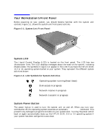 15
15 16
16 17
17 18
18 19
19

