| Section |
Page |
| owner’s guide |
1 |
| owner’s guide |
1 |
| owner’s guide |
1 |
| hp workstation c-class |
1 |
| Printed in USA �� |
1 |
| Manufacturing Part Number:� A7814-90000 |
1 |
| Edition E1001 |
1 |
| © Copyright 2001 |
2 |
| © Copyright 2001 |
2 |
| Hewlett-Packard Company |
2 |
| notice |
2 |
| notice |
2 |
| 1. HP warrants HP hardware, accessories and supplies against defects in materials and workmanship... |
2 |
| 1. HP warrants HP hardware, accessories and supplies against defects in materials and workmanship... |
2 |
| 2. HP warrants that HP software will not fail to execute its programming instructions, for the pe... |
2 |
| 3. HP does not warrant that the operation of HP products will be uninterrupted or error free. If ... |
3 |
| 4. HP products may contain remanufactured parts equivalent to new in performance or may have been... |
3 |
| 5. The warranty period begins on the date of delivery or on the date of installation if installed... |
3 |
| 6. Warranty does not apply to defects resulting from (a) improper or inadequate maintenance or ca... |
3 |
| 7. TO THE EXTENT ALLOWED BY LOCAL LAW, THE ABOVE WARRANTIES ARE EXCLUSIVE AND NO OTHER WARRANTY O... |
3 |
| 8. HP will be liable for damage to tangible property per incident up to the greater of $300,000 o... |
3 |
| 9. TO THE EXTENT ALLOWED BY LOCAL LAW, THE REMEDIES IN THIS WARRANTY STATEMENT ARE CUSTOMER’S SOL... |
3 |
| preface |
17 |
| preface |
17 |
| audience |
17 |
| audience |
17 |
| safety and regulatory statements |
17 |
| safety and regulatory statements |
17 |
| installation notice |
18 |
| installation notice |
18 |
| related manuals |
18 |
| related manuals |
18 |
| • Configuring HP-UX for Peripherals |
18 |
| • Configuring HP-UX for Peripherals |
18 |
| • HP-UX System Administration Tasks |
18 |
| • HP CDE Getting Started Guide |
18 |
| • Managing Systems and Workstations |
18 |
| • Using HP-UX. |
18 |
| • Using Your HP Workstation |
18 |
| revision history |
19 |
| revision history |
19 |
| Edition |
19 |
| Edition |
19 |
| Edition |
19 |
| Revision History |
19 |
| E1001 |
19 |
| E1001 |
19 |
| First Printing |
19 |
| problems, questions, and suggestions |
19 |
| problems, questions, and suggestions |
19 |
| documentation conventions |
20 |
| documentation conventions |
20 |
| <TABLE> |
20 |
| <TABLE BODY> |
20 |
| <TABLE ROW> |
20 |
| user-supplied values |
20 |
| Italic words or characters in syntax and command descriptions represent values that you must supp... |
20 |
| <TABLE ROW> |
20 |
| screen display |
20 |
| Information that the system displays, commands that you must use literally, and path names appear... |
20 |
| <TABLE ROW> |
20 |
| Enter |
20 |
| Keycaps are presented with a special keycap font as shown in the left column. (In this document, ... |
20 |
| electrostatic discharge (ESD) precautions |
20 |
| electrostatic discharge (ESD) precautions |
20 |
| ESD (electrostatic discharge) |
20 |
| Electrostatic discharge (ESD) |
20 |
| • Stand on a static-free mat. |
20 |
| • Stand on a static-free mat. |
20 |
| • Wear a static strap to ensure that any accumulated electrostatic charge is discharged from your... |
20 |
| • Create a common ground for the equipment you are working on by connecting the static-free mat, ... |
20 |
| • Keep uninstalled printed circuit boards in their protective antistatic bags. |
20 |
| • Handle printed circuit boards by their edges, once you have removed them from their protective ... |
20 |
| 1� system overview |
21 |
| 1� system overview |
21 |
| • Product Description |
22 |
| • Product Description |
22 |
| • System Unit Front Panel and Removable Devices |
22 |
| • System Unit Rear Panel Connectors |
22 |
| • Monitors |
22 |
| • Operating System Overview |
22 |
| • Information You Need to Record |
22 |
| • Powering Up Your System. |
22 |
| product description |
23 |
| product description |
23 |
| Product description |
23 |
| HP workstation c-class features |
23 |
| <TABLE> |
23 |
| Table 1�1 HP Workstation C-Class Features |
23 |
| <TABLE HEADING> |
23 |
| <TABLE ROW> |
23 |
| Computer Feature |
23 |
| Description |
23 |
| <TABLE BODY> |
23 |
| <TABLE ROW> |
23 |
| Processor |
23 |
| PA RISC architecture |
23 |
| <TABLE ROW> |
23 |
| Operating System |
23 |
| HP-UX operating system |
23 |
| <TABLE ROW> |
23 |
| User Interface |
23 |
| User interface |
23 |
| Interface, user |
23 |
| HP CDE graphical user interface |
23 |
| <TABLE ROW> |
23 |
| Compatibility |
23 |
| Source and binary code compatible with the c-class product family |
23 |
| <TABLE ROW> |
23 |
| Monitors |
23 |
| List of compatible monitors: |
23 |
| • 19 inch, 1280x1024 and 1600x1200 color, 75Hz |
23 |
| • 19 inch, 1280x1024 and 1600x1200 color, 75Hz |
23 |
| • 21 inch, 1280x1024 (stereo capability) and 1600x1200 color, 75Hz |
23 |
| • 18” Flat Screen Display |
23 |
| <TABLE ROW> |
23 |
| Optional Graphics |
23 |
| Supported graphics devices: |
23 |
| • HP Visualize-EG and Visualize-fx2 Pro (for B1000) |
23 |
| • HP Visualize-EG and Visualize-fx2 Pro (for B1000) |
23 |
| • HP Visualize-EG, Visualize-fx2 Pro and Visualize-fx4 Pro (for C3000) |
23 |
| • HP Visualize Fe |
23 |
| <TABLE ROW> |
23 |
| Main Memory |
23 |
| The c-class computers use 128 MByte and 256 MByte DIMMs to provide a minimum of 128 MBytes and a ... |
23 |
| <TABLE ROW> |
23 |
| Internal Storage Devices |
23 |
| Ultra2 Wide Low-Voltage Differential (LVD) SCSI hard disk drive(s) and a choice of either a flopp... |
23 |
| <TABLE ROW> |
24 |
| Standard Network |
24 |
| RJ45, Twisted Pair 10 BaseT/100 BaseT |
24 |
| <TABLE ROW> |
24 |
| Standard I/O |
24 |
| Standard computer I/O ports: |
24 |
| • Ultra2 W |
24 |
| • Ultra2 W |
24 |
| Fast Narrow Single-Ended SCSI |
24 |
| Fast Narrow Single-Ended SCSI |
24 |
| Parallel port (IEEE 1284) |
24 |
| Parallel port (IEEE 1284) |
24 |
| Universal serial bus (USB) |
24 |
| Universal serial bus (USB) |
24 |
| Serial interface port (RS-232C) |
24 |
| Serial interface port (RS-232C) |
24 |
| • Audio ports (Line in, line out, headset, and microphone in) |
24 |
| <TABLE ROW> |
24 |
| PCI slots |
24 |
| PCI slots |
24 |
| Peripheral component interconnect (PCI) slots |
24 |
| Slot 1: �64 Bit, 5.0V, 33MHz |
24 |
| <TABLE ROW> |
24 |
| Keyboard |
24 |
| Universal Serial Bus (USB) keyboard |
24 |
| <TABLE ROW> |
24 |
| Mouse |
24 |
| Universal Serial Bus (USB) mouse |
24 |
| system unit front panel and removable devices |
25 |
| system unit front panel and removable devices |
25 |
| Controls, front panel |
25 |
| Front panel controls |
25 |
| Panel controls, front |
25 |
| Figure 1�1 System Unit Front Panel Controls |
25 |
| Figure 1�1 System Unit Front Panel Controls |
25 |
| <GRAPHIC> |
26 |
| system LCD |
26 |
| System LCD |
26 |
| Liquid crystal display (LCD) |
26 |
| LCD symbols |
26 |
| Symbols, LCD |
26 |
| Figure 1�2 LCD Symbols |
26 |
| Figure 1�2 LCD Symbols |
26 |
| <GRAPHIC> |
26 |
| system power switch |
26 |
| shutdown -q |
26 |
| Power switch |
26 |
| Switch, power |
26 |
| removable media devices |
27 |
| removable media devices |
27 |
| Floppy disk drive |
27 |
| CD-ROM drive |
27 |
| Media devices, removable |
27 |
| Removable media devices |
27 |
| • CD drive |
27 |
| • CD drive |
27 |
| • Floppy disk drive |
27 |
| NOTE You cannot have two devices of the same type. For example, you cannot have two CD drives, an... |
27 |
| system unit rear panel connectors |
28 |
| system unit rear panel connectors |
28 |
| EMI compliance |
28 |
| 802.3 twisted pair LAN connector |
28 |
| Connector:LAN (802.3 Twisted Pair) |
28 |
| RS-232C serial I/O connector |
28 |
| Connector:RS-232C serial I/O |
28 |
| Ultra2 Wide Low-Voltage Differential SCSI |
28 |
| Fast Narrow Single-Ended SCSI |
28 |
| SCSI:Ultra2 Wide Low-Voltage Differential |
28 |
| SCSI:Fast Narrow Single-Ended |
28 |
| TOC button |
28 |
| Button, TOC |
28 |
| Power cord connector |
28 |
| Connector:Power cord |
28 |
| Connector:Ultra2 Wide Low-Voltage Differential SCSI |
28 |
| Connector:Fast Narrow Single-Ended SCSI |
28 |
| Audio connectors |
28 |
| Connector:Audio |
28 |
| Connector:USB |
28 |
| USB connectors |
28 |
| Parallel connector |
28 |
| Parallel connector, IEEE 1284 |
28 |
| IEEE 1284, parallel connector |
28 |
| Connector:Parallel (IEEE 1284) |
28 |
| • Audio connectors (including headphones and microphone) |
28 |
| • Audio connectors (including headphones and microphone) |
28 |
| • USB keyboard and mouse connectors |
28 |
| • HP parallel IEEE 1284 I/O connector |
28 |
| • 802.3 TP (Twisted Pair) LAN connector |
28 |
| • RS-232C serial I/O connectors |
28 |
| • SCSI connectors including Ultra2 Wide Low-Voltage Differential and Ultra Narrow Single-Ended SCSI |
28 |
| • TOC (transfer of control) button |
28 |
| • Power cord connector |
28 |
| NOTE To maintain FCC/EMI compliance, verify that all cables are fully seated and properly fastened. |
28 |
| Rear panel connectors, system unit |
29 |
| System unit rear panel connectors |
29 |
| I/O card slots, rear panel |
29 |
| Rear panel:I/O card slots |
29 |
| Rear panel:Serial interface port |
29 |
| USB ports |
29 |
| Rear panel:USB ports |
29 |
| Line input jack |
29 |
| Rear panel:Line input jack |
29 |
| Rear panel:Line output jack |
29 |
| Line output jack |
29 |
| Microphone jack |
29 |
| Rear panel:Microphone jack |
29 |
| Rear panel:Headphones jack |
29 |
| Headphones jack |
29 |
| Rear panel:Ultra2 Wide LVD SCSI |
29 |
| Ultra2 Wide Low-Voltage Differential SCSI |
29 |
| Fast Narrow Single-Ended SCSI |
29 |
| Rear panel:Fast Narrow Single-Ended SCSI |
29 |
| Rear panel:Power input |
29 |
| Power input |
29 |
| Figure 1�3 |
29 |
| NOTE The Ultra Narrow Single-Ended SCSI and Ultra2 Wide Low-Voltage Differential SCSI connectors ... |
29 |
| Figure 1�3 System Unit Rear Panel Connectors |
29 |
| Figure 1�3 System Unit Rear Panel Connectors |
29 |
| <GRAPHIC> |
30 |
| audio connectors |
30 |
| Connector:Audio |
30 |
| Audio connectors |
30 |
| Figure 1�4 Audio Connectors |
30 |
| Figure 1�4 Audio Connectors |
30 |
| <GRAPHIC> |
30 |
| Electrical specifications, audio |
30 |
| Specifications, audio electrical |
30 |
| <TABLE> |
31 |
| Table 1�2 Audio Electrical Specifications |
31 |
| <TABLE BODY> |
31 |
| <TABLE ROW> |
31 |
| Frequency Response |
31 |
| 25Hz to 20kHz |
31 |
| <TABLE ROW> |
31 |
| Max Input Sensitivity/Impedance |
31 |
| Line in Microphone |
31 |
| Line in Microphone |
31 |
| 2.8Vp-p/10Kohm 40mVp-p/47Kohm |
31 |
| 2.8Vp-p/10Kohm 40mVp-p/47Kohm |
31 |
| 2.8Vp-p/10Kohm 40mVp-p/47Kohm |
31 |
| <TABLE ROW> |
31 |
| Max Output Level/Impedance |
31 |
| Line out Headphone Speaker (internal) |
31 |
| Line out Headphone Speaker (internal) |
31 |
| 2.8Vp-p/920ohm 5.6Vp-p/110ohm n.a. |
31 |
| 2.8Vp-p/920ohm 5.6Vp-p/110ohm n.a. |
31 |
| 2.8Vp-p/920ohm 5.6Vp-p/110ohm n.a. |
31 |
| USB connectors |
31 |
| USB connectors |
31 |
| Connector:USB |
31 |
| USB connectors |
31 |
| keyboard |
31 |
| keyboard |
31 |
| USB:Keyboard |
31 |
| Keyboard, USB |
31 |
| hp scroll mouse |
32 |
| hp scroll mouse |
32 |
| Scroll mouse, HP |
32 |
| HP scroll mouse, USB |
32 |
| USB:HP scroll mouse |
32 |
| hp hub for USB devices |
32 |
| hp hub for USB devices |
32 |
| HP hub, USB |
32 |
| Hub, HP USB devices |
32 |
| USB:HP Hub |
32 |
| hp parallel i/o connector |
32 |
| hp parallel i/o connector |
32 |
| Parallel I/O connector |
32 |
| Connector:Parallel (IEEE 1284) |
32 |
| 802.3 network connectors |
32 |
| 802.3 network connectors |
32 |
| Connector:802.3 twisted pair LAN |
32 |
| 802.3 twisted pair LAN connector |
32 |
| RS-232C serial input/output connector |
33 |
| RS-232C serial input/output connector |
33 |
| Connector:RS-232C serial I/O |
33 |
| RS-232C serial I/O connector |
33 |
| <TABLE> |
33 |
| Table 1�3 Serial I/O Pins |
33 |
| <TABLE HEADING> |
33 |
| <TABLE ROW> |
33 |
| Pin No. |
33 |
| Signal |
33 |
| Description |
33 |
| <TABLE BODY> |
33 |
| <TABLE ROW> |
33 |
| 1 |
33 |
| DCD |
33 |
| Data Carrier Detect |
33 |
| <TABLE ROW> |
33 |
| 2 |
33 |
| RXD |
33 |
| Receive Data |
33 |
| <TABLE ROW> |
33 |
| 3 |
33 |
| TXD |
33 |
| Transmit Data |
33 |
| <TABLE ROW> |
33 |
| 4 |
33 |
| DTR |
33 |
| Data Terminal Ready |
33 |
| <TABLE ROW> |
33 |
| 5 |
33 |
| GND |
33 |
| Ground |
33 |
| <TABLE ROW> |
33 |
| 6 |
33 |
| DSR |
33 |
| Data Set Ready |
33 |
| <TABLE ROW> |
33 |
| 7 |
33 |
| RTS |
33 |
| Request To Send |
33 |
| <TABLE ROW> |
33 |
| 8 |
33 |
| CTS |
33 |
| Clear To Send |
33 |
| <TABLE ROW> |
33 |
| 9 |
33 |
| RI |
33 |
| Ring Indicator |
33 |
| SCSI connectors |
34 |
| SCSI connectors |
34 |
| Connector:Ultra2 Wide Low-Voltage Differential SCSI |
34 |
| Connector:Fast Narrow Single-Ended SCSI |
34 |
| Fast Narrow Single-Ended SCSI |
34 |
| Ultra2 Wide Low-Voltage Differential SCSI |
34 |
| NOTE When attaching external Ultra Narrow Single-Ended SCSI (NSE SCSI) and Ultra2 Wide Low-Voltag... |
34 |
| power cord connector |
34 |
| power cord connector |
34 |
| Connector:Power cord |
34 |
| security loop |
35 |
| security loop |
35 |
| Security loop |
35 |
| Loop, security |
35 |
| Figure 1�5 Security Loop Components |
35 |
| Figure 1�5 Security Loop Components |
35 |
| <GRAPHIC> |
36 |
| locking your system unit’s left-side panel |
36 |
| 1. Make sure the system unit’s left side panel is closed. See |
36 |
| 1. Make sure the system unit’s left side panel is closed. See |
36 |
| Figure 1�6 Closed Left-Side Panel |
36 |
| Figure 1�6 Closed Left-Side Panel |
36 |
| <GRAPHIC> |
36 |
| 3. Lock the padlock. Your system unit’s left side panel is now secure. |
36 |
| memory |
37 |
| memory |
37 |
| Memory, main |
37 |
| monitors |
38 |
| monitors |
38 |
| Monitors |
38 |
| • 19-inch, 1280µ±²³µ¶·¸¹°½¥1024 color, 75Hz (A4575A) |
38 |
| • 19-inch, 1280µ±²³µ¶·¸¹°½¥1024 color, 75Hz (A4575A) |
38 |
| • 19-inch, 1600¥1200 color, 75Hz (A4575A) |
38 |
| • 21-inch, 1280¥1024 color (stereo capability), 75Hz (A4576A) |
38 |
| • 21-inch, 1600¥1200 color, 75Hz (A4576A) |
38 |
| operating system overview |
39 |
| operating system overview |
39 |
| Instant ignition |
39 |
| Operating system overview |
39 |
| System overview, operating |
39 |
| information you need to record |
40 |
| information you need to record |
40 |
| LAN station ID |
40 |
| Internet protocol (IP) address |
40 |
| Subnetwork mask |
40 |
| Mask, subnetwork |
40 |
| • LAN Station ID |
40 |
| • LAN Station ID |
40 |
| • Internet Protocol (IP) address |
40 |
| • Subnetwork mask |
40 |
| LAN station ID |
40 |
| LAN station ID |
40 |
| LAN station ID |
40 |
| IP address and subnetwork mask information |
40 |
| IP address and subnetwork mask information |
40 |
| IP address |
40 |
| powering up your system |
41 |
| powering up your system |
41 |
| • Your computer has been “ignited;” that is, the HP’s Instant Ignition process has installed the ... |
41 |
| • Your computer has been “ignited;” that is, the HP’s Instant Ignition process has installed the ... |
41 |
| • Your computer has not been “ignited;” that is, the HP’s Instant Ignition process has not instal... |
41 |
| getting required information |
42 |
| getting required information |
42 |
| NOTE If you are not the system administrator for your workstation, and you do not know the requir... |
42 |
| • Host name _____________________________________________ The host name is sometimes called the “... |
42 |
| • Host name _____________________________________________ The host name is sometimes called the “... |
42 |
| • Internet Protocol address ________________________________ You will need this address if you ar... |
42 |
| • Time zone ______________________________________________ This is the time zone where the workst... |
42 |
| • Optional networking parameters Ask your system administrator if you need to configure these par... |
42 |
| <TABLE> |
42 |
| <TABLE BODY> |
42 |
| <TABLE ROW> |
42 |
| Subnetwork mask |
42 |
| __________________ |
42 |
| <TABLE ROW> |
42 |
| Network gateway IP address |
42 |
| __________________ |
42 |
| <TABLE ROW> |
42 |
| Local domain name |
42 |
| __________________ |
42 |
| <TABLE ROW> |
42 |
| DNS server host name |
42 |
| __________________ |
42 |
| <TABLE ROW> |
42 |
| DNS server IP address |
42 |
| __________________ |
42 |
| <TABLE ROW> |
42 |
| Network Information Service domain name |
42 |
| __________________ |
42 |
| • Optional font server parameters You need to supply these parameters if you want the workstation... |
43 |
| • Optional font server parameters You need to supply these parameters if you want the workstation... |
43 |
| <TABLE> |
43 |
| <TABLE BODY> |
43 |
| <TABLE ROW> |
43 |
| Font server name |
43 |
| __________________ |
43 |
| <TABLE ROW> |
43 |
| Font server IP address |
43 |
| __________________ |
43 |
| turning on the power |
44 |
| turning on the power |
44 |
| 1. Turn on the monitor and any external peripherals (for example, printers) connected to the work... |
44 |
| 1. Turn on the monitor and any external peripherals (for example, printers) connected to the work... |
44 |
| 2. Turn on the workstation. The workstation will run a series of self-tests. |
44 |
| 3. After two or three minutes, a series of messages are displayed as various hardware and softwar... |
44 |
| 4. A series of windows appears requesting the information you gathered in the previous section, s... |
44 |
| NOTE You should enter the host name when requested; otherwise, you will get an error message when... |
44 |
| 5. You are now asked if you want to set a root password. Specify the root password now. The root ... |
44 |
| 6. When you have finished answering all of the questions, the workstation completes its start-up ... |
44 |
| 7. Log into your first CDE session as |
45 |
| NOTE You must log into the first session as |
45 |
| 8. Use the System Administration Manager (SAM) to set-up user accounts. |
45 |
| documentation |
45 |
| documentation |
45 |
| 2� using your CD drive |
47 |
| 2� using your CD drive |
47 |
| • Operating the CD Drive |
48 |
| • Operating the CD Drive |
48 |
| • Mounting and Unmounting a CD |
48 |
| • Verifying the CD Drive Operation |
48 |
| • Configuring the CD Driver |
48 |
| • Audio Control for the CD Drive |
48 |
| • CD Media Description |
48 |
| NOTE Be sure you have read and understand the information on mounting and unmounting CDs before y... |
48 |
| NOTE This chapter requires you to be superuser ( |
48 |
| CD media description |
49 |
| CD media description |
49 |
| CD-ROM media |
49 |
| Media, CD-ROM |
49 |
| CAUTION Handle CDs by the edges only. Always be sure a CD is either in the CD drive or its protec... |
49 |
| caring for CDs |
49 |
| caring for CDs |
49 |
| Care, CD-ROM |
49 |
| CD-ROM, care |
49 |
| • Use CDs in a clean environment to prevent dust particles from scratching disc surfaces. |
49 |
| • Use CDs in a clean environment to prevent dust particles from scratching disc surfaces. |
49 |
| • Store CDs in a cool, dry place to prevent moisture and heat damage. |
49 |
| • Do not try to clean the surface of a CD with cleaning solvents, as some cleaning solvents may d... |
49 |
| operating the CD drive |
50 |
| operating the CD drive |
50 |
| CD drive, operating |
50 |
| CD drive |
50 |
| CD drive |
50 |
| CD drive |
50 |
| controls and features |
51 |
| controls and features |
51 |
| CD drive, controls and features |
51 |
| Figure 2�1 |
51 |
| NOTE The exact positioning of CD Drive controls/features may vary depending on the model of the d... |
51 |
| Figure 2�1 CD Drive Controls and Features |
51 |
| Figure 2�1 CD Drive Controls and Features |
51 |
| <GRAPHIC> |
51 |
| Table 2�1 CD Drive Operating Controls and Features |
51 |
| <TABLE HEADING> |
51 |
| <TABLE ROW> |
51 |
| Control/Feature |
51 |
| Purpose |
51 |
| <TABLE BODY> |
51 |
| <TABLE ROW> |
51 |
| Busy Indicator |
51 |
| The Busy Indicator blinks during a data transfer. |
51 |
| <TABLE ROW> |
51 |
| Eject Button |
51 |
| The Eject Button when pressed opens the Disk Tray for removal or insertion of a disk. When the dr... |
51 |
| <TABLE ROW> |
51 |
| Emergency Eject |
51 |
| You can open the Disk Tray when the computer does not have power by inserting the end of a paper ... |
51 |
| <TABLE ROW> |
51 |
| Disk Tray |
51 |
| The Disk Tray holds the CD. This style of CD drive does not use a disk caddy. |
51 |
| loading and unloading a CD |
52 |
| loading and unloading a CD |
52 |
| CD-ROM, loading and unloading |
52 |
| NOTE To use the file system on a CD, you must be superuser ( |
52 |
| loading a CD |
52 |
| loading a CD |
52 |
| Loading, CD-ROM |
52 |
| 1. Press and release the eject button on the CD drive. The disk tray opens as shown in |
52 |
| 1. Press and release the eject button on the CD drive. The disk tray opens as shown in |
52 |
| Figure 2�2 Open CD Tray |
52 |
| Figure 2�2 Open CD Tray |
52 |
| <GRAPHIC> |
53 |
| Figure 2�3 Placing the CD in the Disk Tray |
53 |
| Figure 2�3 Placing the CD in the Disk Tray |
53 |
| <GRAPHIC> |
53 |
| Figure 2�4 Closed Disk Tray |
53 |
| Figure 2�4 Closed Disk Tray |
53 |
| <GRAPHIC> |
54 |
| unloading a CD |
54 |
| Unloading, CD-ROM |
54 |
| 1. Press and release the eject button on the CD drive to open the disk tray. |
54 |
| 1. Press and release the eject button on the CD drive to open the disk tray. |
54 |
| 2. Grasp the disk by the edges and lift it out of the disk tray. |
54 |
| 3. Press the Eject Button to close the disk tray. |
54 |
| locating help |
54 |
| locating help |
54 |
| mounting and unmounting a CD |
55 |
| mounting and unmounting a CD |
55 |
| CD-ROM, mounting and unmounting |
55 |
| mounting a CD using SAM |
55 |
| mounting a CD using SAM |
55 |
| Mounting, CD-ROM |
55 |
| 1. Log in as |
55 |
| 1. Log in as |
55 |
| 2. Move the mouse pointer to the Application Manager control for tools and click the left mouse b... |
55 |
| <GRAPHIC> |
56 |
| <GRAPHIC> |
56 |
| <GRAPHIC> |
56 |
| <GRAPHIC> |
57 |
| <GRAPHIC> |
57 |
| 7. Click on Add in the Actions menu. For this example you will select the item Not Using the Logi... |
57 |
| 8. Enter the mount directory name (for example, /disk1) in the Mount Directory field of the Add D... |
57 |
| 9. Click on the Modify Defaults... button. In the Modify Defaults window, select the Read Only it... |
57 |
| 10. Click on the OK button in the Add Disk without LVM window. You will need to wait for a short ... |
57 |
| unmounting a CD using SAM |
58 |
| unmounting a CD using SAM |
58 |
| Unmounting, CD-ROM |
58 |
| NOTE Before you unmount a CD, make sure that your working directory is set to a directory other t... |
58 |
| 1. Log in as |
58 |
| 1. Log in as |
58 |
| 2. Move the mouse pointer to the Application Manager control for tools and click the left mouse b... |
58 |
| <GRAPHIC> |
58 |
| <GRAPHIC> |
59 |
| <GRAPHIC> |
59 |
| <GRAPHIC> |
59 |
| <GRAPHIC> |
59 |
| 7. Click on Remove in the Actions menu. In the window that next appears, click on the Yes button.... |
60 |
| verifying the CD drive operation |
61 |
| verifying the CD drive operation |
61 |
| Verifying, CD drive |
61 |
| CD drive, verifying |
61 |
| 1. Log in as |
61 |
| 1. Log in as |
61 |
| 2. Type the following command at the shell prompt and press Enter: ���/usr/sbin/ioscan -d sdisk |
61 |
| H/W Path ����Class ������������Description =============================================== 10/0/1... |
61 |
| configuring the CD driver |
62 |
| configuring the CD driver |
62 |
| Floppy driver, configuring |
62 |
| Configuring, floppy driver |
62 |
| • Managing Systems and Workgroups |
62 |
| • Managing Systems and Workgroups |
62 |
| • Using HP-UX |
62 |
| audio control for the CD drive |
63 |
| audio control for the CD drive |
63 |
| installing the xmcd utility |
63 |
| installing the xmcd utility |
63 |
| 1. Log in as root. |
63 |
| 1. Log in as root. |
63 |
| 2. Type the previously given URL into the entry box on your web browser and press Enter. |
63 |
| 3. Select the menu item labeled Downloads found on the xmcd homepage. |
63 |
| 4. Scroll down to the section “Select your platform:” on the Downloads web page and select the it... |
63 |
| 5. Wait for a few seconds for the Save As... pop-up window to appear. In this window, click in th... |
63 |
| 6. Follow the instructions in the section “Instructions to unpack xmcd binary” found on this Bina... |
63 |
| using the xmcd utility |
64 |
| using the xmcd utility |
64 |
| 1. Load the audio CD. See the section “loading a CD” in this chapter. |
64 |
| 1. Load the audio CD. See the section “loading a CD” in this chapter. |
64 |
| 2. Insert the headphone plug into the headphone jack located on the back of your system unit. |
64 |
| 3. Click on the Audio icon located on your HP CDE control panel. |
64 |
| 4. Click on the Monitoring checkbox in the Audio window to select it. Then select the Output menu... |
65 |
| 5. Start the utility by typing xmcd at the prompt and pressing Enter. |
65 |
| 3� using your 3.5-inch floppy disk drive |
67 |
| 3� using your 3.5-inch floppy disk drive |
67 |
| • Operating the Floppy Drive |
68 |
| • Operating the Floppy Drive |
68 |
| • Verifying the Floppy Drive Configuration |
68 |
| • Additional Floppy Drive Information. |
68 |
| NOTE When examples of user input are given in this chapter, enter them at the command-line prompt... |
68 |
| operating the floppy drive |
69 |
| operating the floppy drive |
69 |
| Floppy disk drive:Operating |
69 |
| floppy disk drive |
69 |
| floppy disk drive |
69 |
| controls and features |
69 |
| controls and features |
69 |
| Floppy disk drive:Controls and features |
69 |
| Figure 3�1 |
69 |
| Figure 3�1 Floppy Disk Drive Controls and Features |
69 |
| Figure 3�1 Floppy Disk Drive Controls and Features |
69 |
| <GRAPHIC> |
69 |
| Table 3�1 Floppy Disk Drive Operating Controls and Features |
69 |
| <TABLE HEADING> |
69 |
| <TABLE ROW> |
69 |
| Control/Feature |
69 |
| Purpose |
69 |
| <TABLE BODY> |
69 |
| <TABLE ROW> |
69 |
| Busy Indicator |
69 |
| Floppy disk drive:Busy indicator |
69 |
| Busy indicator |
69 |
| The Busy Indicator illuminates during a data access operation and blinks during a data transfer. |
69 |
| <TABLE ROW> |
69 |
| Eject Button |
69 |
| The Eject Button, when pressed, ejects the floppy diskette from the floppy disk drive. |
69 |
| using the floppy diskette |
70 |
| using the floppy diskette |
70 |
| Floppy diskette |
70 |
| setting the write-protect tab on a diskette |
70 |
| setting the write-protect tab on a diskette |
70 |
| Floppy diskette write-protect tab |
70 |
| Write-protect tab, floppy diskette |
70 |
| Figure 3�2 Setting the Write-Protect Tab on a Floppy Diskette |
70 |
| Figure 3�2 Setting the Write-Protect Tab on a Floppy Diskette |
70 |
| <GRAPHIC> |
70 |
| inserting and removing a diskette |
71 |
| inserting and removing a diskette |
71 |
| Floppy diskette:Inserting |
71 |
| Floppy diskette:Removing |
71 |
| 1. Insert the diskette into the drive, as shown in |
71 |
| 1. Insert the diskette into the drive, as shown in |
71 |
| Figure 3�3 Inserting and Removing a Floppy Diskette |
71 |
| Figure 3�3 Inserting and Removing a Floppy Diskette |
71 |
| <GRAPHIC> |
71 |
| 3. Remove the diskette by pressing the eject button (see |
71 |
| using device files |
71 |
| using device files |
71 |
| Device files, using |
71 |
| NOTE The device file names depend on the naming conventions of your particular system. |
71 |
| 1. Log in as |
72 |
| 1. Log in as |
72 |
| 2. Move the mouse pointer to the Application Manager control for tools and click the left mouse b... |
72 |
| <GRAPHIC> |
72 |
| <GRAPHIC> |
73 |
| <GRAPHIC> |
73 |
| <GRAPHIC> |
73 |
| <GRAPHIC> |
73 |
| 7. Select the Actions menu and then select the menu item View More Information. A window opens wi... |
73 |
| formatting a new diskette |
74 |
| formatting a new diskette |
74 |
| Floppy diskette:Formatting |
74 |
| Formatting, floppy diskette |
74 |
| 1. Log in as root. |
74 |
| 1. Log in as root. |
74 |
| 2. Make sure that the write-protect tab on the floppy diskette is in the write position, as shown in |
74 |
| 3. Insert the diskette into the floppy disk drive. |
74 |
| 4. Type the following at the prompt and press Enter: ����mediainit -f 16 devicefile where 16 is t... |
74 |
| transferring data to and from a floppy diskette |
75 |
| transferring data to and from a floppy diskette |
75 |
| Floppy diskette:Transferring data |
75 |
| Transferring data, floppy diskette |
75 |
| Saving files, floppy diskette |
75 |
| Floppy diskette:Saving files |
75 |
| saving files to a floppy diskette |
75 |
| saving files to a floppy diskette |
75 |
| 1. Check the write-protect tab on the floppy diskette to ensure that it is in the write position. |
75 |
| 1. Check the write-protect tab on the floppy diskette to ensure that it is in the write position. |
75 |
| 2. Load the formatted floppy diskette into the disk drive. |
75 |
| 3. Type the following command in a terminal window at the prompt and press |
75 |
| restoring files from a floppy diskette to your system |
76 |
| restoring files from a floppy diskette to your system |
76 |
| Floppy diskette:Restoring files |
76 |
| Restoring files, floppy diskette |
76 |
| 1. Load the floppy diskette into the disk drive. |
76 |
| 1. Load the floppy diskette into the disk drive. |
76 |
| 2. Type the following command in a terminal window at the prompt and press Enter: ���cd directory... |
76 |
| 3. Enter the following command at the prompt and press Enter: ���tar -xvf devicefile pathname whe... |
76 |
| listing the files on a floppy diskette |
76 |
| listing the files on a floppy diskette |
76 |
| Listing files, floppy diskette |
76 |
| Floppy diskette, listing files |
76 |
| 1. Load the floppy diskette into the disk drive. |
76 |
| 1. Load the floppy diskette into the disk drive. |
76 |
| 2. Enter the following command in a terminal window at the prompt and press Enter: tar -tvf devic... |
76 |
| troubleshooting |
76 |
| troubleshooting |
76 |
| verifying the floppy drive configuration |
77 |
| verifying the floppy drive configuration |
77 |
| ioscan |
77 |
| floppy |
77 |
| Floppy disk drive:Verifying configuration |
77 |
| Class���I��H/W Path������Driver���S/W�State �H/W�Type��Description ==============================... |
77 |
| Class���I��H/W Path������Driver���S/W�State �H/W�Type��Description ==============================... |
77 |
| additional floppy drive information |
78 |
| additional floppy drive information |
78 |
| configuring the floppy driver |
78 |
| configuring the floppy driver |
78 |
| Floppy driver, configuring |
78 |
| Configuring, floppy driver |
78 |
| • Managing Systems and Workgroups |
78 |
| • Managing Systems and Workgroups |
78 |
| • Using HP-UX |
78 |
| for more information |
78 |
| for more information |
78 |
| man |
78 |
| tar |
78 |
| cpio |
78 |
| doscp |
78 |
| dosls |
78 |
| floppy |
78 |
| 4� SCSI connections |
81 |
| 4� SCSI connections |
81 |
| • SCSI bus differences |
82 |
| • SCSI bus differences |
82 |
| • SCSI Restrictions |
82 |
| • Determining SCSI Bus Length |
82 |
| • Assigning SCSI Device IDs |
82 |
| • Connecting to the SCSI Ports |
82 |
| NOTE When attaching external SCSI devices, be sure to terminate the last device on the external S... |
82 |
| SCSI bus differences |
83 |
| SCSI bus differences |
83 |
| SCSI bus:Differences |
83 |
| CAUTION Currently Hewlett-Packard does not support mixing Ultra Narrow Single-Ended and Ultra2 Wi... |
83 |
| <TABLE> |
83 |
| Table 4�1 SCSI Bus Differences |
83 |
| <TABLE HEADING> |
83 |
| <TABLE ROW> |
83 |
| Type |
83 |
| Data Transfer Rate |
83 |
| Data Bus Width |
83 |
| Available SCSI Addresses |
83 |
| Maximum Cable Length |
83 |
| Device Physical Location |
83 |
| <TABLE BODY> |
83 |
| <TABLE ROW> |
83 |
| Ultra Narrow Single-Ended |
83 |
| Up to 20 Mbytes/sec |
83 |
| 8 bits |
83 |
| 0 through 6 |
83 |
| 3.0 meters (9.84 feet) |
83 |
| External |
83 |
| <TABLE ROW> |
83 |
| Ultra2 Wide Low-Voltage Differential |
83 |
| Up to 80 Mbytes/sec |
83 |
| 16 bits |
83 |
| 0 through 6; 8 through 15 |
83 |
| 12 meters (39.37 feet) |
83 |
| Internal and external |
83 |
| SCSI restrictions |
84 |
| SCSI restrictions |
84 |
| SCSI bus:Restrictions |
84 |
| • Cables |
84 |
| • Cables |
84 |
| • Terminators |
84 |
| • Number of Devices Per SCSI Bus |
84 |
| • Considerations for Selecting SCSI Devices |
84 |
| SCSI restrictions:cables |
84 |
| SCSI restrictions:cables |
84 |
| SCSI restrictions:cables |
84 |
| SCSI cables |
84 |
| Cables, SCSI |
84 |
| <TABLE> |
84 |
| Table 4�2 Ultra Narrow Single-Ended SCSI Cables |
84 |
| <TABLE HEADING> |
84 |
| <TABLE ROW> |
84 |
| Cable Number |
84 |
| Cable Length |
84 |
| Description |
84 |
| <TABLE BODY> |
84 |
| <TABLE ROW> |
84 |
| C2955A |
84 |
| 0.5m |
84 |
| 50-pin HDTS to 50-pin HDTS |
84 |
| <TABLE ROW> |
84 |
| C2908A |
84 |
| 1.0m |
84 |
| <TABLE ROW> |
84 |
| C2956A |
84 |
| 1.5m |
84 |
| <TABLE ROW> |
84 |
| C2957A |
84 |
| 2.0m |
84 |
| <TABLE> |
85 |
| Table 4�3 Ultra2 Wide Low-Voltage Differential SCSI Cables |
85 |
| <TABLE HEADING> |
85 |
| <TABLE ROW> |
85 |
| Cable Number |
85 |
| Cable Length |
85 |
| Description |
85 |
| <TABLE BODY> |
85 |
| <TABLE ROW> |
85 |
| C2978A |
85 |
| 0.5m |
85 |
| 68-pin HDTS to 68-pin HDTS |
85 |
| <TABLE ROW> |
85 |
| C2979A |
85 |
| 1.5m |
85 |
| <TABLE ROW> |
85 |
| C2911B |
85 |
| 1.0m |
85 |
| <TABLE ROW> |
85 |
| C2924B |
85 |
| 2.5m |
85 |
| <TABLE ROW> |
85 |
| C2361A |
85 |
| 1.0m |
85 |
| 68-pin VHDCI to 68-pin HDTS |
85 |
| <TABLE ROW> |
85 |
| C2362A |
85 |
| 2.5m |
85 |
| <TABLE ROW> |
85 |
| C2363A |
85 |
| 10.0m |
85 |
| <TABLE ROW> |
85 |
| C2365A |
85 |
| 5.0m |
85 |
| CAUTION SCSI cables approved by HP are designed to function within the SCSI tolerances for HP dev... |
85 |
| NOTE See “scsi bus length constraints” later in this chapter to determine the total length of you... |
85 |
| terminators |
86 |
| terminators |
86 |
| Terminators, SCSI |
86 |
| SCSI terminators |
86 |
| Ultra2 Wide Low-Voltage Differential SCSI |
86 |
| Fast Narrow Single-Ended SCSI |
86 |
| CAUTION It is necessary to put a terminator on unused SCSI connectors on the back panel of the sy... |
86 |
| number of devices per SCSI bus |
86 |
| number of devices per SCSI bus |
86 |
| SCSI bus:Configuration constraints |
86 |
| • Ultra Narrow Single-Ended SCSI bus |
86 |
| • Ultra Narrow Single-Ended SCSI bus |
86 |
| • Ultra2 Wide Low-Voltage Differential SCSI bus |
86 |
| considerations for selecting SCSI devices |
86 |
| considerations for selecting SCSI devices |
86 |
| Global Engineering Documents 15 Inverness Way East Englewood, CO 80112-5704 800-854-7179 or 303-3... |
87 |
| SCSI bus length constraints |
88 |
| SCSI bus length constraints |
88 |
| SCSI bus:Length constraints |
88 |
| ultra narrow single-ended SCSI bus length |
88 |
| ultra narrow single-ended SCSI bus length |
88 |
| Fast Narrow Single-Ended SCSI |
88 |
| NOTE When calculating the total Ultra Narrow Single-Ended SCSI cable/bus/trace length used extern... |
88 |
| • For a total of one to four devices being connected to the NSE SCSI bus the total length of cabl... |
88 |
| • For a total of one to four devices being connected to the NSE SCSI bus the total length of cabl... |
88 |
| • For a total of five to eight devices being connected to the NSE SCSI bus the total length of ca... |
88 |
| Ultra2 wide low-voltage differential SCSI bus length |
89 |
| Ultra2 wide low-voltage differential SCSI bus length |
89 |
| Ultra2 Wide Low-Voltage Differential SCSI |
89 |
| NOTE When calculating the total Ultra2 Wide Low-Voltage Differential SCSI cable/bus/trace length ... |
89 |
| assigning SCSI device IDs |
90 |
| assigning SCSI device IDs |
90 |
| SCSI device IDs:assigning |
90 |
| SCSI bus:Device IDs |
90 |
| ioscan |
90 |
| Class I H/W Path Driver S/W State H/W Type Description |
90 |
| assigning Ultra narrow single-ended SCSI device IDs |
91 |
| assigning Ultra narrow single-ended SCSI device IDs |
91 |
| SCSI device IDs:Fast Narrow Single-Ended |
91 |
| SCSI device |
91 |
| SCSI device |
91 |
| SCSI device |
91 |
| 10/0/15/0.2.0 |
91 |
| NSE SCSI |
91 |
| NSE SCSI |
91 |
| 10/0/15/0.2.0 |
91 |
| SCSI ID 2 |
91 |
| SCSI ID 2 |
91 |
| 10/0/15/0.2.0 |
91 |
| CAUTION Do not use SCSI device ID 7 for any device. It is reserved for the built-in SCSI bus cont... |
91 |
| assigning Ultra2 wide low-voltage differential SCSI device IDs |
92 |
| assigning Ultra2 wide low-voltage differential SCSI device IDs |
92 |
| SCSI device IDs:Ultra2 Wide Low-Voltage Differential |
92 |
| SCSI device |
92 |
| SCSI device |
92 |
| SCSI device |
92 |
| 10/0/15/1.5.0 |
92 |
| LVD SCSI |
92 |
| LVD SCSI |
92 |
| 10/0/15/1.5.0 |
92 |
| SCSI ID 5 |
92 |
| SCSI ID 5 |
92 |
| 10/0/15/1.5.0 |
92 |
| CAUTION Do not use SCSI device ID 7 for any device. It is reserved for the built-in SCSI bus cont... |
92 |
| connecting to the SCSI ports |
93 |
| connecting to the SCSI ports |
93 |
| system SCSI port connection |
93 |
| system SCSI port connection |
93 |
| SCSI ports:Connecting |
93 |
| • Ultra Narrow Single-Ended SCSI (NSE SCSI) connector |
93 |
| • Ultra Narrow Single-Ended SCSI (NSE SCSI) connector |
93 |
| • Ultra2 Wide Low-Voltage Differential SCSI (LVD SCSI) connector |
93 |
| <GRAPHIC> |
93 |
| NOTE It is necessary to put a terminator on unused SCSI connectors on the back panel, or the last... |
93 |
| 5� changing your computer hardware configuration |
95 |
| 5� changing your computer hardware configuration |
95 |
| • System Unit Front Panel |
96 |
| • System Unit Front Panel |
96 |
| • Left Side Panel of the System Unit |
96 |
| • System Unit Power Supply |
96 |
| • I/O Cards |
96 |
| • System Unit Fans |
96 |
| • Removable Media Devices |
96 |
| • Hard Disk Drives |
96 |
| • Memory Cards |
96 |
| • Changing Your Monitor Type |
96 |
| CAUTION Always wear a properly grounded wrist strap when reconfiguring your computer with interna... |
96 |
| WARNING Always unplug the system unit power cord from the electrical outlet or power source befor... |
96 |
| • Light-duty flat blade screwdriver with 150mm (6 inch) long shaft |
96 |
| • Light-duty flat blade screwdriver with 150mm (6 inch) long shaft |
96 |
| • T-10 and T-15 Torx drivers. Note that the screws these drivers are used on have a recessed slot... |
96 |
| • Needle-nose pliers |
96 |
| NOTE Many of the HP-UX commands in this chapter will require that you become superuser (root). If... |
96 |
| system unit front panel |
97 |
| system unit front panel |
97 |
| Hardware configuration:System unit front panel |
97 |
| System unit front panel |
97 |
| opening the system unit front panel |
97 |
| opening the system unit front panel |
97 |
| 1. Power off the system, and unplug the system unit power cord from the electrical outlet. Note t... |
97 |
| 1. Power off the system, and unplug the system unit power cord from the electrical outlet. Note t... |
97 |
| 2. Attach the static-grounding wrist strap by following the instructions on the package. Attach t... |
97 |
| Bezel latch button |
97 |
| Bezel latch button |
97 |
| Bezel lock |
97 |
| Figure 5�1 Opening the Front Panel |
97 |
| Figure 5�1 Opening the Front Panel |
97 |
| <GRAPHIC> |
98 |
| closing the system unit front panel |
98 |
| closing the system unit front panel |
98 |
| 1. Locate the hinges on the left side of the front panel, and insert them into the holes located ... |
98 |
| 1. Locate the hinges on the left side of the front panel, and insert them into the holes located ... |
98 |
| 2. Rotate the front panel inward until you hear the two latch buttons snap in place. The front pa... |
98 |
| 3. Plug in the system unit power cord, and power on the system. |
98 |
| left side panel of the system unit |
99 |
| left side panel of the system unit |
99 |
| Hardware configuration:Left side panel of the system unit |
99 |
| Left side panel of the system unit |
99 |
| opening the left side panel of the system unit |
99 |
| opening the left side panel of the system unit |
99 |
| NOTE When you remove the left side panel, the system unit’s safety interlock release pin will com... |
99 |
| 1. Power off the system, and unplug the system unit power cord from the electrical outlet. |
99 |
| 1. Power off the system, and unplug the system unit power cord from the electrical outlet. |
99 |
| 2. Attach the static-grounding wrist strap by following the instructions on the package. Attach t... |
99 |
| 3. Turn the computer around so its back is facing you. On the right edge of the computer, there a... |
99 |
| Safety interlock:Switch |
100 |
| Safety interlock:Switch |
100 |
| Safety interlock:Release pin |
100 |
| EMI gasket |
100 |
| Figure 5�2 Opening the Left Side Panel of the System Unit |
100 |
| Figure 5�2 Opening the Left Side Panel of the System Unit |
100 |
| <GRAPHIC> |
100 |
| closing the left side panel of the system unit |
101 |
| closing the left side panel of the system unit |
101 |
| 1. Hold the left side panel so that the top and bottom hinge hooks can be inserted into their hin... |
101 |
| 1. Hold the left side panel so that the top and bottom hinge hooks can be inserted into their hin... |
101 |
| 2. Swing the back edge of the panel toward the system unit’s back edge and press the outside edge... |
101 |
| 3. Secure the side panel in place with the two T-15 Torx thumbscrews you previously removed, and ... |
101 |
| system unit power supply |
102 |
| system unit power supply |
102 |
| Hardware configuration:System unit power supply |
102 |
| System unit power supply |
102 |
| Power supply |
102 |
| WARNING To prevent injury, you need to unplug the system unit’s power cord from the electrical ou... |
102 |
| propping up the power supply |
102 |
| propping up the power supply |
102 |
| 1. Lay the system unit on its right side (using the front panel as your reference) and on a cushi... |
102 |
| 1. Lay the system unit on its right side (using the front panel as your reference) and on a cushi... |
102 |
| 2. Open the left side panel of the system unit by following the procedure in the section “opening... |
102 |
| 3. Unscrew the two captive screws on the power supply chassis as shown in |
102 |
| Figure 5�3 Unscrewing the Power Supply Captive Screws |
102 |
| Figure 5�3 Unscrewing the Power Supply Captive Screws |
102 |
| <GRAPHIC> |
103 |
| Figure 5�4 Propping Up the Power Supply |
103 |
| Figure 5�4 Propping Up the Power Supply |
103 |
| <GRAPHIC> |
104 |
| closing the system unit after propping up the power supply |
104 |
| i/o cards |
105 |
| i/o cards |
105 |
| I/O card:Slot number and capabilities |
105 |
| Figure 5�5 PCI Card Slot Numbering and Capabilities |
105 |
| Figure 5�5 PCI Card Slot Numbering and Capabilities |
105 |
| <GRAPHIC> |
105 |
| Figure 5�6 I/O Slot Numbering |
106 |
| Figure 5�6 I/O Slot Numbering |
106 |
| <GRAPHIC> |
106 |
| removing i/o cards |
106 |
| I/O card:Removing |
106 |
| 1. Power off the system, and unplug the system unit power cord from the electrical outlet. Note t... |
106 |
| 1. Power off the system, and unplug the system unit power cord from the electrical outlet. Note t... |
106 |
| 2. Open the side panel of the system unit as explained in the section “opening the left side pane... |
106 |
| 3. Pull evenly in the direction of the arrow on both PULL tabs of the I/O card retainer to remove... |
107 |
| Figure 5�7 Removing the I/O Card Retainer |
107 |
| Figure 5�7 Removing the I/O Card Retainer |
107 |
| <GRAPHIC> |
107 |
| Figure 5�8 Removing the I/O Card |
107 |
| Figure 5�8 Removing the I/O Card |
107 |
| <GRAPHIC> |
107 |
| installing i/o cards |
108 |
| installing i/o cards |
108 |
| I/O card:Installing |
108 |
| NOTE Slots two and four are the graphics card slots. The primary graphics card slot is slot numbe... |
108 |
| 1. Open the left side panel of the system unit as explained in the section “opening the left side... |
108 |
| 1. Open the left side panel of the system unit as explained in the section “opening the left side... |
108 |
| 2. Locate the appropriate slot for the I/O card that is to be installed. See |
108 |
| 3. Unscrew the T-15 Torx screw and remove the bulkhead blank of the slot you have chosen. If no b... |
108 |
| 4. Pull evenly in the direction of the arrow on both PULL tabs of the I/O card retainer to remove... |
108 |
| 5. Insert the I/O card into the slot you have chosen with the bulkhead appropriately positioned. See |
108 |
| 6. Replace the I/O card retainer by placing the bottom retainer hook in the slot on the air divid... |
108 |
| 7. Close the left side panel of the system unit by following the procedure in the section “closin... |
108 |
| system unit fans |
109 |
| system unit fans |
109 |
| System unit fans |
109 |
| Fan:I/O card area |
109 |
| Fan:CPU area |
109 |
| Fan:Hard disk drive area |
109 |
| Figure 5�9 Fan Cooling Areas for the System Unit |
109 |
| Figure 5�9 Fan Cooling Areas for the System Unit |
109 |
| <GRAPHIC> |
109 |
| removing the fan from the hard disk drive area |
110 |
| removing the fan from the hard disk drive area |
110 |
| Hard disk drive area fan:Removing |
110 |
| 1. Lay the system unit on its side and on a cushioned surface to avoid cosmetic damage to the sys... |
110 |
| 1. Lay the system unit on its side and on a cushioned surface to avoid cosmetic damage to the sys... |
110 |
| 2. Remove the system unit’s side panel. See the section “opening the left side panel of the syste... |
110 |
| 3. Prop up the power supply. See the section “propping up the power supply” in this chapter. |
110 |
| 4. Lift up on the handle of the fan bracket to remove the fan. See |
111 |
| Figure 5�10 Removing the Fan from the Hard Disk Drive Chassis |
111 |
| Figure 5�10 Removing the Fan from the Hard Disk Drive Chassis |
111 |
| <GRAPHIC> |
112 |
| replacing the hard disk drive fan |
112 |
| Hard disk drive area fan:Replacing |
112 |
| 1. Position the fan bracket so that the top alignment tabs will fit around the two hard disk driv... |
112 |
| 1. Position the fan bracket so that the top alignment tabs will fit around the two hard disk driv... |
112 |
| 2. Close the system unit as explained in the section “propping up the power supply” in this chapter. |
112 |
| removable media devices |
113 |
| removable media devices |
113 |
| Removable media devices |
113 |
| Media devices, removable |
113 |
| • CD drive |
113 |
| • CD drive |
113 |
| • 3.5-inch floppy disk drive. |
113 |
| installing a CD drive |
113 |
| installing a CD drive |
113 |
| WARNING Turn the system unit off and unplug the power cord before installing the CD drive. |
113 |
| CD drive:Installing |
113 |
| CAUTION CD drives are susceptible to mechanical and electronic shock. When handling the drive, al... |
113 |
| 1. Perform the procedures in the sections “opening the system unit front panel” and “opening the ... |
113 |
| 1. Perform the procedures in the sections “opening the system unit front panel” and “opening the ... |
113 |
| 2. Remove the CD drive bay’s rear cover by unscrewing the T-15 Torx/slotted screw as shown in |
114 |
| Figure 5�11 Removing the CD Drive Bay’s Rear Cover |
114 |
| Figure 5�11 Removing the CD Drive Bay’s Rear Cover |
114 |
| <GRAPHIC> |
114 |
| Figure 5�12 Front of System Unit with the Front Panel Removed |
114 |
| Figure 5�12 Front of System Unit with the Front Panel Removed |
114 |
| <GRAPHIC> |
115 |
| Figure 5�13 Removing the CD Drive Bracket and Blank |
115 |
| Figure 5�13 Removing the CD Drive Bracket and Blank |
115 |
| <GRAPHIC> |
115 |
| 5. Remove the CD drive from its shipping container and check to see that the jumper on the back o... |
116 |
| Figure 5�14 Installing the CD Drive |
116 |
| Figure 5�14 Installing the CD Drive |
116 |
| <GRAPHIC> |
116 |
| 7. Plug the audio, ATAPI and power cables into their appropriate connectors. Note that the connec... |
117 |
| Figure 5�15 Plugging in the Audio, ATAPI and Power Cables |
117 |
| Figure 5�15 Plugging in the Audio, ATAPI and Power Cables |
117 |
| <GRAPHIC> |
117 |
| Figure 5�16 Tightening the Bracket Screws |
117 |
| Figure 5�16 Tightening the Bracket Screws |
117 |
| <GRAPHIC> |
118 |
| Figure 5�17 Replacing the CD Drive Bay’s Rear Cover |
118 |
| Figure 5�17 Replacing the CD Drive Bay’s Rear Cover |
118 |
| <GRAPHIC> |
118 |
| 11. Complete the installation of the CD drive by replacing the front and side panels of the syste... |
118 |
| 12. Verify that the CD drive is recognized by the system. See the section “verifying the cd drive... |
118 |
| removing a CD drive |
119 |
| removing a CD drive |
119 |
| CD drive:Removing |
119 |
| WARNING Turn the system unit off and unplug the power cord before removing the CD drive. |
119 |
| CAUTION CD drives are susceptible to mechanical and electronic shock. When handling the drive, al... |
119 |
| 1. Perform the procedures in the sections “opening the system unit front panel” and “opening the ... |
119 |
| 1. Perform the procedures in the sections “opening the system unit front panel” and “opening the ... |
119 |
| 2. Remove the CD drive bay’s rear cover by unscrewing the T-15 Torx/slotted screw as shown in |
120 |
| Figure 5�18 Removing the CD Drive Bay’s Rear Cover |
120 |
| Figure 5�18 Removing the CD Drive Bay’s Rear Cover |
120 |
| <GRAPHIC> |
121 |
| Figure 5�19 Front of the System Unit with the Front Panel Removed |
121 |
| Figure 5�19 Front of the System Unit with the Front Panel Removed |
121 |
| <GRAPHIC> |
122 |
| Figure 5�20 Removing the CD Drive |
122 |
| Figure 5�20 Removing the CD Drive |
122 |
| <GRAPHIC> |
123 |
| Figure 5�21 Installing the CD Drive Blank |
123 |
| Figure 5�21 Installing the CD Drive Blank |
123 |
| <GRAPHIC> |
124 |
| Figure 5�22 Tightening the Bracket Screws |
124 |
| Figure 5�22 Tightening the Bracket Screws |
124 |
| <GRAPHIC> |
124 |
| Figure 5�23 Replacing the CD Drive Bay’s Rear Cover |
124 |
| Figure 5�23 Replacing the CD Drive Bay’s Rear Cover |
124 |
| <GRAPHIC> |
125 |
| 9. Replace the left side panel and front panel of the system unit as explained in the sections “c... |
125 |
| installing a floppy disk drive |
125 |
| installing a floppy disk drive |
125 |
| Floppy disk drive:Installing |
125 |
| WARNING Turn the system unit off and unplug the power cord before installing the floppy disk drive. |
125 |
| CAUTION Floppy disk drives are susceptible to mechanical and electronic shock. When handling the ... |
125 |
| 1. Perform the procedures in the sections “opening the system unit front panel” and “opening the ... |
125 |
| 1. Perform the procedures in the sections “opening the system unit front panel” and “opening the ... |
125 |
| 2. Remove the floppy disk drive bay’s rear cover by unscrewing the T-15 Torx screw as shown in |
126 |
| Figure 5�24 Removing the Floppy Disk Drive Bay’s Rear Cover |
126 |
| Figure 5�24 Removing the Floppy Disk Drive Bay’s Rear Cover |
126 |
| <GRAPHIC> |
127 |
| Figure 5�25 Front of System Unit with the Front Panel Removed |
127 |
| Figure 5�25 Front of System Unit with the Front Panel Removed |
127 |
| <GRAPHIC> |
128 |
| Figure 5�26 Removing the Floppy Disk Bracket and Blank |
128 |
| Figure 5�26 Removing the Floppy Disk Bracket and Blank |
128 |
| <GRAPHIC> |
128 |
| 5. Remove the floppy disk drive from its shipping container. Using the four T-10 Torx/slotted bla... |
129 |
| Figure 5�27 Installing the Floppy Disk Drive |
129 |
| Figure 5�27 Installing the Floppy Disk Drive |
129 |
| <GRAPHIC> |
130 |
| 7. Plug the floppy power cable into its connector. Next, plug the data cable into its connector. ... |
130 |
| Figure 5�28 Plugging In the Floppy Data and Power Cables |
130 |
| Figure 5�28 Plugging In the Floppy Data and Power Cables |
130 |
| <GRAPHIC> |
130 |
| Figure 5�29 Tightening the Bracket Screws |
130 |
| Figure 5�29 Tightening the Bracket Screws |
130 |
| <GRAPHIC> |
131 |
| Figure 5�30 Replacing the Floppy Disk Drive Bay’s Rear Cover |
131 |
| Figure 5�30 Replacing the Floppy Disk Drive Bay’s Rear Cover |
131 |
| <GRAPHIC> |
131 |
| 11. Complete the installation of the floppy disk drive by replacing the front and side panels of ... |
131 |
| 12. Verify that the floppy disk drive is recognized by the system. See the section “verifying the... |
131 |
| removing a floppy disk drive |
132 |
| removing a floppy disk drive |
132 |
| Floppy disk drive:Removing |
132 |
| WARNING Turn the system unit off and unplug the power cord before removing the floppy disk drive. |
132 |
| CAUTION Floppy disk drives are susceptible to mechanical and electronic shock. When handling the ... |
132 |
| 1. Perform the procedures in the sections “opening the system unit front panel” and “opening the ... |
132 |
| 1. Perform the procedures in the sections “opening the system unit front panel” and “opening the ... |
132 |
| 2. Remove the floppy disk drive bay’s rear cover by unscrewing the T-15 Torx/slotted screw as sho... |
133 |
| Figure 5�31 Removing the Floppy Disk Drive Bay’s Rear Cover |
133 |
| Figure 5�31 Removing the Floppy Disk Drive Bay’s Rear Cover |
133 |
| <GRAPHIC> |
134 |
| Figure 5�32 Front of System Unit with the Front Panel Removed |
134 |
| Figure 5�32 Front of System Unit with the Front Panel Removed |
134 |
| <GRAPHIC> |
135 |
| Figure 5�33 Removing the Floppy Disk Drive |
135 |
| Figure 5�33 Removing the Floppy Disk Drive |
135 |
| <GRAPHIC> |
136 |
| Figure 5�34 Installing the Floppy Disk Blank and Bracket |
136 |
| Figure 5�34 Installing the Floppy Disk Blank and Bracket |
136 |
| <GRAPHIC> |
136 |
| 7. Tighten the two floppy disk bracket screws as shown in |
137 |
| Figure 5�35 Tightening the Bracket Screws |
137 |
| Figure 5�35 Tightening the Bracket Screws |
137 |
| <GRAPHIC> |
137 |
| Figure 5�36 Replacing the Rear Floppy Disk Drive Bay’s Cover |
137 |
| Figure 5�36 Replacing the Rear Floppy Disk Drive Bay’s Cover |
137 |
| <GRAPHIC> |
138 |
| 10. Complete the removal of the floppy disk drive by replacing the front and side panels of the s... |
138 |
| hard disk drives |
139 |
| hard disk drives |
139 |
| CAUTION Hard disk drives are susceptible to mechanical and electronic shock. When handling the dr... |
139 |
| installing a hard disk drive |
140 |
| installing a hard disk drive |
140 |
| Hard disk drive:Installing |
140 |
| NOTE If you are installing a hard disk drive, you will need to mount it and create a file system ... |
140 |
| 1. Open the front panel of your system unit using the instructions found in the section “opening ... |
140 |
| 1. Open the front panel of your system unit using the instructions found in the section “opening ... |
140 |
| Figure 5�37 The Hard Drive Slots |
140 |
| Figure 5�37 The Hard Drive Slots |
140 |
| <GRAPHIC> |
141 |
| Figure 5�38 Removing the Hard Drive Bracket |
141 |
| Figure 5�38 Removing the Hard Drive Bracket |
141 |
| <GRAPHIC> |
141 |
| 4. Insert the T-15 Torx Hard Disk Mounting Screws through the rubber mounting grommets and into t... |
142 |
| Figure 5�39 Inserting the Hard Disk Drive |
142 |
| Figure 5�39 Inserting the Hard Disk Drive |
142 |
| <GRAPHIC> |
142 |
| removing a hard disk drive |
143 |
| removing a hard disk drive |
143 |
| Hard disk drive:Removing |
143 |
| NOTE If you are removing a hard disk drive that has a mounted file system on it, you will need to... |
143 |
| 1. Open the front panel of you system unit using the instructions found in the section “opening t... |
143 |
| 1. Open the front panel of you system unit using the instructions found in the section “opening t... |
143 |
| Figure 5�40 The Hard Drive Slots |
143 |
| Figure 5�40 The Hard Drive Slots |
143 |
| <GRAPHIC> |
144 |
| Figure 5�41 Removing the Hard Disk Drive |
144 |
| Figure 5�41 Removing the Hard Disk Drive |
144 |
| <GRAPHIC> |
145 |
| Figure 5�42 Removing the Hard Disk Drive from Its Bracket |
145 |
| Figure 5�42 Removing the Hard Disk Drive from Its Bracket |
145 |
| <GRAPHIC> |
146 |
| Figure 5�43 Replacing the Hard Disk Drive Bracket |
146 |
| Figure 5�43 Replacing the Hard Disk Drive Bracket |
146 |
| <GRAPHIC> |
147 |
| configuring a hard disk drive as a file system |
147 |
| Hard disk drive:Configuring |
147 |
| adding a hard disk drive as a file system using SAM |
147 |
| adding a hard disk drive as a file system using SAM |
147 |
| 1. Log in as root. |
147 |
| 1. Log in as root. |
147 |
| 2. Move the mouse pointer to the Application Manager control for tools and click the left mouse b... |
147 |
| <GRAPHIC> |
147 |
| <GRAPHIC> |
148 |
| <GRAPHIC> |
148 |
| <GRAPHIC> |
148 |
| <GRAPHIC> |
148 |
| 7. Click on Add in the Actions menu. For this example you will select the item Not Using the Logi... |
148 |
| 8. Enter the mount directory name (for example, /disk1) in the Mount Directory field of the Add D... |
149 |
| 9. Click on the OK button in the Add Disk without LVM window. You will need to wait for a short t... |
149 |
| Removing a Hard Disk Drive as a File System Using SAM |
149 |
| Removing a Hard Disk Drive as a File System Using SAM |
149 |
| 1. Log in as root. |
149 |
| 1. Log in as root. |
149 |
| 2. Move the mouse pointer to the Application Manager control for tools and click the left mouse b... |
149 |
| <GRAPHIC> |
149 |
| <GRAPHIC> |
150 |
| <GRAPHIC> |
150 |
| <GRAPHIC> |
150 |
| <GRAPHIC> |
150 |
| 7. Click on Remove in the Actions menu. In the window that next appears, click on the Yes button.... |
151 |
| memory cards |
152 |
| memory cards |
152 |
| Memory cards (DIMM cards) |
152 |
| • Use the procedure described in “the boot console interface” chapter to determine the current me... |
152 |
| • Use the procedure described in “the boot console interface” chapter to determine the current me... |
152 |
| • Read over the steps in the section “installing additional memory” before you begin the installa... |
152 |
| • Inserts DIMMs in the order shown. Please refer to |
152 |
| • Be sure you understand the proper orientation for DIMMs when inserting them into their connecto... |
152 |
| • Use the “boot console interface” to verify that the computer recognizes the additional DIMMs wh... |
152 |
| installing additional memory |
152 |
| installing additional memory |
152 |
| Memory card:Installing |
152 |
| NOTE Lay the system on its right side (using the system unit’s front panel as a reference) as sho... |
152 |
| 1. Open the side panel of the system unit as explained in the section “opening the left side pane... |
152 |
| 1. Open the side panel of the system unit as explained in the section “opening the left side pane... |
152 |
| 2. Prop up the system unit power supply as explained in the section “propping up the system unit ... |
153 |
| Figure 5�44 Propping Up the Power Supply |
153 |
| Figure 5�44 Propping Up the Power Supply |
153 |
| <GRAPHIC> |
154 |
| 4. Remove the hard disk drive fan as explained in the section “removing the fan from the hard dis... |
154 |
| Figure 5�45 Memory Card Slot Numbers and Loading Sequence |
154 |
| Figure 5�45 Memory Card Slot Numbers and Loading Sequence |
154 |
| <GRAPHIC> |
154 |
| 5. Press downward on the ejector tabs located on both sides of the DIMM connector. See |
155 |
| Figure 5�46 Installing Memory Cards |
155 |
| Figure 5�46 Installing Memory Cards |
155 |
| <GRAPHIC> |
155 |
| 7. Press firmly and evenly on the DIMM card to ensure that it seats properly, and replace the har... |
155 |
| 8. Replace the left side panel as explained in the section “closing the system unit after proppin... |
155 |
| 9. Verify that this installation was successful by following the steps in the section “displaying... |
155 |
| removing memory |
156 |
| removing memory |
156 |
| Memory card:Removing |
156 |
| NOTE Lay the system on its right side (using the system unit’s front panel as a reference) as sho... |
156 |
| 1. Open the side panel of the system unit as explained in the section “opening the left side pane... |
156 |
| 1. Open the side panel of the system unit as explained in the section “opening the left side pane... |
156 |
| 2. Prop up the system unit power supply as explained in the section “propping up the system unit ... |
156 |
| Figure 5�47 Propping Up the Power Supply |
156 |
| Figure 5�47 Propping Up the Power Supply |
156 |
| <GRAPHIC> |
156 |
| 4. Press downward on the ejector tabs located on both sides of the DIMM connector. See Figure |
157 |
| Figure 5�48 Removing Memory Cards |
157 |
| Figure 5�48 Removing Memory Cards |
157 |
| <GRAPHIC> |
157 |
| 6. Install the remaining DIMM cards in the correct order. See |
157 |
| 7. Replace the hard disk drive fan as explained in the section “replacing the hard disk drive fan... |
157 |
| 8. Replace the left side panel as explained in the section “closing the system unit after proppin... |
157 |
| 9. Verify that this removal was successful by following the steps in Chapter 6 of this book, “the... |
157 |
| changing your monitor type |
158 |
| changing your monitor type |
158 |
| Monitor type:Changing |
158 |
| setting the monitor type at power on |
158 |
| setting the monitor type at power on |
158 |
| Monitor type:Setting at power on |
158 |
| 1. Press the Tab key after your keyboard’s Num Lock light comes on during the boot process to ini... |
158 |
| 1. Press the Tab key after your keyboard’s Num Lock light comes on during the boot process to ini... |
158 |
| 2. Select one of the monitor types listed on the screen and press Enter. If your monitor is not l... |
158 |
| 3. Answer yes, by pressing Y, to the system query to confirm your selection. Note that if you do ... |
158 |
| setting the monitor type from the boot console interface |
158 |
| setting the monitor type from the boot console interface |
158 |
| Monitor type:Setting from boot console interface |
158 |
| setting the monitor type using SAM |
159 |
| setting the monitor type using SAM |
159 |
| Monitor type:Setting using SAM |
159 |
| 1. Log in as |
159 |
| 1. Log in as |
159 |
| 2. Move the mouse pointer to the Application Manager control for tools and click the left mouse b... |
159 |
| <GRAPHIC> |
159 |
| <GRAPHIC> |
160 |
| <GRAPHIC> |
160 |
| <GRAPHIC> |
160 |
| <GRAPHIC> |
160 |
| 7. Click on the monitor icon in the Monitor Configuration window whose monitor type you want to s... |
160 |
| 8. Select the action Modify Monitor Type from the Action menu. You will see a window with a list ... |
161 |
| 9. Select an entry from the list in the Modify Monitor window. In that same window, select the ch... |
161 |
| 10. Connect your monitor cable to the graphics card you selected, and your screen contents will a... |
161 |
| troubleshooting monitor problems |
162 |
| troubleshooting monitor problems |
162 |
| Monitor problems, troubleshooting |
162 |
| 1. Turn system power off. |
162 |
| 1. Turn system power off. |
162 |
| 2. Disconnect the computer keyboard connector from the system rear panel. |
162 |
| 3. Connect a serial terminal emulator to the Serial 1 connector (the left serial connector) on th... |
162 |
| 4. Power on the system. The system will now display the console to the terminal connected to Seri... |
162 |
| 5. Set the monitor type and path using the Boot Console Interface. For information on doing this ... |
162 |
| 6� the boot console interface |
163 |
| 6� the boot console interface |
163 |
| • Boot Console Interface Features |
164 |
| • Boot Console Interface Features |
164 |
| • Accessing the Boot Console Interface |
164 |
| • Booting Your Computer |
164 |
| • Searching for Bootable Media |
164 |
| • Resetting Your Computer |
164 |
| • Displaying and Setting Paths |
164 |
| • Displaying and Setting the Monitor Type |
164 |
| • Changing the Console to an External Terminal |
164 |
| • Displaying the Current Memory Configuration |
164 |
| • Displaying the Status of the System I/O |
164 |
| • Setting the Auto Boot and Auto Search Flags |
164 |
| • Displaying and Setting the Security Mode |
164 |
| • Displaying and Setting the Fastboot Mode |
164 |
| • Displaying the LAN Station Address |
164 |
| • Displaying System Information |
164 |
| boot console interface features |
165 |
| boot console interface features |
165 |
| Boot console interface features |
165 |
| • Boot your computer |
165 |
| • Boot your computer |
165 |
| • Search for bootable media |
165 |
| • Reset your computer |
165 |
| • Display and set boot paths |
165 |
| • Display and set your monitor type |
165 |
| • Display memory configuration information |
165 |
| • Display the status of the PCI slots |
165 |
| • Set Auto Boot, Auto Search and Auto Start |
165 |
| • Set Fastboot |
165 |
| • Display LAN information |
165 |
| • Display system information |
165 |
| Boot console interface menu:Configuration |
167 |
| Boot console interface menu:Information |
168 |
| Boot console interface menu:Service |
169 |
| accessing the boot console interface |
170 |
| accessing the boot console interface |
170 |
| Boot console interface, accessing |
170 |
| NOTE This procedure should be done by a system administrator or superuser with root log in permis... |
170 |
| 1. Close any files and applications on your computer. |
170 |
| 1. Close any files and applications on your computer. |
170 |
| 2. Press the power switch on the front panel of the system unit. |
170 |
| NOTE There is no need to log in as root and execute the shutdown -q command to shut down the HP-U... |
170 |
| 3. Power on your computer after your system has completely shut down. If auto boot is turned off,... |
170 |
| NOTE If you are using a power-saving monitor, you will have less than 10 seconds from the time th... |
171 |
| 4. Press a key. You will then see the message: ����Boot terminated The Main Menu of the boot cons... |
171 |
| booting your computer |
172 |
| booting your computer |
172 |
| Booting computer |
172 |
| Computer, booting |
172 |
| boot |
172 |
| boot |
172 |
| boot |
172 |
| • If you do not know which device you want to boot from, then type the following at the prompt an... |
172 |
| • If you wish to interact with the Initial System Loader (ISL) before booting you computer, follo... |
173 |
| • If you do not know which media in your file systems have bootable operating systems, you can fi... |
174 |
| searching for bootable media |
175 |
| searching for bootable media |
175 |
| search |
175 |
| Bootable media, searching |
175 |
| Ctrl S |
175 |
| Ctrl S |
175 |
| Ctrl S |
175 |
| Temporarily suspends the search. |
175 |
| Ctrl Q |
175 |
| Ctrl Q |
175 |
| Continues the search. |
175 |
| Any Other Key |
175 |
| Any Other Key |
175 |
| Stops the search. |
175 |
| fwscsi |
175 |
| fwscsi |
175 |
| fwscsi |
175 |
| Is the built-in Ultra2 Wide LVD SCSI bus. |
175 |
| scsi |
175 |
| scsi |
175 |
| Is the built-in Fast Narrow Single-Ended SCSI bus. |
175 |
| lan |
175 |
| lan |
175 |
| Is all connections to the built-in LAN. |
175 |
| pcin |
175 |
| pcin |
175 |
| Is an optional SCSI interface in slot number n. |
175 |
| ide |
175 |
| ide |
175 |
| Is a built-in IDE bus. |
175 |
| resetting your computer |
176 |
| resetting your computer |
176 |
| Computer, resetting |
176 |
| reset |
176 |
| displaying and setting paths |
177 |
| displaying and setting paths |
177 |
| path |
177 |
| Paths, displaying and setting |
177 |
| Hardware address |
177 |
| <TABLE> |
177 |
| Table 6�1 System Paths |
177 |
| <TABLE HEADING> |
177 |
| <TABLE ROW> |
177 |
| Path Type |
177 |
| Device |
177 |
| <TABLE BODY> |
177 |
| <TABLE ROW> |
177 |
| primary or pri |
177 |
| Your computer’s default boot device (usually the root disk) |
177 |
| <TABLE ROW> |
177 |
| alternate or alt |
177 |
| Your computer’s alternate boot device (usually a DDS-format tape device) |
177 |
| <TABLE ROW> |
177 |
| console or con |
177 |
| Your computer’s primary display device |
177 |
| <TABLE ROW> |
177 |
| keyboard or key |
177 |
| Your computer’s primary input ASCII device |
177 |
| Boot path, mnemonic style notation |
177 |
| <TABLE> |
177 |
| Table 6�2 Mnemonic Style Notation for Boot Paths |
177 |
| <TABLE HEADING> |
177 |
| <TABLE ROW> |
177 |
| I/O Type |
177 |
| Specification Format |
177 |
| <TABLE BODY> |
177 |
| <TABLE ROW> |
177 |
| Built-in LVD SCSI |
177 |
| fwscsi.scsi_address.logical_unit_number |
177 |
| fwscsi.scsi_address.logical_unit_number |
177 |
| <TABLE ROW> |
177 |
| Built-in NSE SCSI |
177 |
| scsi.scsi_address.logical_unit_number |
177 |
| scsi.scsi_address.logical_unit_number |
177 |
| <TABLE ROW> |
177 |
| Built-in LAN |
177 |
| lan.server_address.init_timeout.io_timeout |
177 |
| lan |
177 |
| lan |
177 |
| <TABLE ROW> |
177 |
| Built-in IDE |
177 |
| ide |
177 |
| ide |
177 |
| displaying and setting the monitor type |
179 |
| displaying and setting the monitor type |
179 |
| Monitor type:Displaying and setting |
179 |
| the monitor command |
179 |
| the monitor command |
179 |
| monitor |
179 |
| NOTE The |
179 |
| graphics(1) |
180 |
| graphics(1) |
180 |
| graphics(1) |
180 |
| graphics(1) |
180 |
| Graphics adapter installed in slot 1 |
180 |
| graphics(2) |
180 |
| graphics(2) |
180 |
| graphics(2) |
180 |
| Graphics adapter installed in slot 2 (primary slot) |
180 |
| graphics(3) |
180 |
| graphics(3) |
180 |
| graphics(3) |
180 |
| Graphics adapter installed in slot 3 |
180 |
| graphics(4) |
180 |
| graphics(4) |
180 |
| graphics(4) |
180 |
| Graphics adapter installed in slot 4 (secondary slot) |
180 |
| graphics(5) |
180 |
| graphics(5) |
180 |
| graphics(5) |
180 |
| Graphics adapter installed in slot 5 |
180 |
| graphics(6) |
180 |
| graphics(6) |
180 |
| graphics(6) |
180 |
| Graphics adapter installed in slot 6 |
180 |
| displaying the current monitor configuration |
181 |
| displaying the current monitor configuration |
181 |
| Monitor configuration, displaying |
181 |
| setting the monitor type |
182 |
| setting the monitor type |
182 |
| Monitor type:Setting |
182 |
| MONITOR INFORMATION Path�������Slot�Head�Type����Size����Freq�Class ----�������----�----�----��--... |
182 |
| setting the monitor type with SAM |
183 |
| setting the monitor type with SAM |
183 |
| Monitor type:Setting using SAM |
183 |
| 1. Log in as |
183 |
| 1. Log in as |
183 |
| 2. Move the mouse pointer to the Application Manager control for tools and click the left mouse b... |
184 |
| <GRAPHIC> |
184 |
| <GRAPHIC> |
184 |
| <GRAPHIC> |
185 |
| <GRAPHIC> |
185 |
| <GRAPHIC> |
185 |
| 7. Click on the monitor icon in the Monitor Configuration window whose monitor type you want to s... |
185 |
| 8. Select the action Modify Monitor Type from the Actions menu. You will see a window with a list... |
185 |
| 9. Select an entry from the list in the Modify Monitor window. In that same window, select the ch... |
185 |
| 10. Connect your monitor cable to the graphics card you selected, and your screen contents will a... |
185 |
| setting the monitor type at power on |
186 |
| setting the monitor type at power on |
186 |
| Monitor type:Setting at power on |
186 |
| NOTE It takes a short amount of time (approximately 40 seconds) after powering on the computer be... |
186 |
| Path�������Slot��Head��Type�����Size�����Freq��Class ----------�----��----��----�------------�---... |
186 |
| To select a new Graphics Monitor Type press the <TAB> key now, otherwise EXIT by entering any oth... |
187 |
| troubleshooting monitor problems |
187 |
| troubleshooting monitor problems |
187 |
| Monitor, troubleshooting |
187 |
| 1. Turn system power off. |
187 |
| 1. Turn system power off. |
187 |
| 2. Disconnect the computer keyboard connector from the system rear panel. |
187 |
| 3. Connect a serial terminal emulator to the Serial 1 connector (the left serial connector) on th... |
187 |
| 4. Power on the system. The system will now display the console to the terminal connected to Seri... |
187 |
| 5. Set the monitor type and path using the Boot Console Interface. For information on doing this ... |
187 |
| changing the console to an external terminal |
188 |
| changing the console to an external terminal |
188 |
| Console, changing to an external terminal |
188 |
| Terminal, changing the console to an external |
188 |
| 1. Turn the system’s power off. |
188 |
| 1. Turn the system’s power off. |
188 |
| 2. Disconnect the USB keyboard connector from the system rear panel. |
188 |
| 3. Connect a serial terminal to the “Serial 1” connector on the system back panel. Configure the ... |
188 |
| 4. Power on the system. |
188 |
| displaying the current memory configuration |
189 |
| displaying the current memory configuration |
189 |
| Memory configuration, displaying |
189 |
| memory |
189 |
| memory information sample |
190 |
| memory information sample |
190 |
| Memory information sample |
190 |
| displaying the status of the system i/o |
191 |
| displaying the status of the system i/o |
191 |
| io |
191 |
| I/O, displaying the status of the system |
191 |
| I/O MODULE INFORMATION ������������ �����������������������������������������������IODC��IODC Pat... |
191 |
| setting the auto boot and auto search flags |
192 |
| setting the auto boot and auto search flags |
192 |
| auto boot |
192 |
| auto search |
192 |
| Auto boot, setting |
192 |
| Auto search, setting |
192 |
| Primary boot path (can be set by the user) |
193 |
| Primary boot path (can be set by the user) |
193 |
| Alternate boot path (can be set by the user) |
193 |
| Low-voltage differential SCSI (built-in) |
193 |
| PCI 1 through PCI 6 (plug-in interface cards) |
193 |
| Narrow single-ended SCSI (built-in) |
193 |
| LAN (built-in) |
193 |
| displaying and setting the security mode |
194 |
| displaying and setting the security mode |
194 |
| secure |
194 |
| Security mode:Setting |
194 |
| Security mode:Displaying |
194 |
| displaying and setting the fastboot mode |
195 |
| displaying and setting the fastboot mode |
195 |
| fastboot |
195 |
| Fastboot mode:Setting |
195 |
| Fastboot mode:Displaying |
195 |
| displaying the lan station address |
196 |
| displaying the lan station address |
196 |
| LAN station address, displaying |
196 |
| lanaddress |
196 |
| displaying system information |
197 |
| displaying system information |
197 |
| all |
197 |
| System information, displaying |
197 |
| Information, displaying system |
197 |
| 7� solving problems |
199 |
| 7� solving problems |
199 |
| • Common Problems and Solutions |
200 |
| • Common Problems and Solutions |
200 |
| • Dealing with a Boot Failure |
200 |
| • Memory Failures |
200 |
| • LCD Information |
200 |
| • Running System Verification Tests. |
200 |
| NOTE This chapter requires you to log in as |
200 |
| common problems and solutions |
201 |
| common problems and solutions |
201 |
| Common:Problems |
201 |
| Common:Solutions |
201 |
| Powering up the system:Problem |
201 |
| Problem:Powering up the system |
201 |
| Powering up the system:Solution |
201 |
| Solution:Powering up the system |
201 |
| <TABLE> |
201 |
| Table 7�1 Problems Powering Up the System |
201 |
| <TABLE HEADING> |
201 |
| <TABLE ROW> |
201 |
| Problem |
201 |
| Solution |
201 |
| <TABLE BODY> |
201 |
| <TABLE ROW> |
201 |
| The LCD screen does not light up. |
201 |
| Make sure all AC power cables are connected securely to the system. Make sure the power cord is p... |
201 |
| <TABLE ROW> |
201 |
| The LCD screen lights up , but the screen is blank |
201 |
| Make sure the LCD control cable is properly connected inside the system unit. |
201 |
| <TABLE ROW> |
201 |
| LCD messages |
201 |
| See “LCD information” later in this chapter. |
201 |
| <TABLE ROW> |
201 |
| If problems persist, contact your system administrator or call your designated service representa... |
201 |
| <TABLE> |
202 |
| Table 7�2 Problems Loading and Booting the Operating System |
202 |
| Problem:Loading and booting the operating system |
202 |
| Booting and loading the operating system:Problem |
202 |
| Booting and loading the operating system:Solution |
202 |
| Solution:Loading and booting the operating system |
202 |
| Loading and booting the operating system:Solution |
202 |
| Loading and booting the operating system:Problem |
202 |
| <TABLE HEADING> |
202 |
| <TABLE ROW> |
202 |
| Problem |
202 |
| Solution |
202 |
| <TABLE BODY> |
202 |
| <TABLE ROW> |
202 |
| The LCD screen is lit, and text appears on the screen, but more than two minutes have passed with... |
202 |
| Make sure that all SCSI devices are set to the proper SCSI ID. (See Appendix C for default SCSI I... |
202 |
| <TABLE ROW> |
202 |
| The system stops or hangs while booting. |
202 |
| Follow the instructions in “dealing with a boot failure” later in this chapter. If the LCD displa... |
202 |
| <TABLE ROW> |
202 |
| If problems persist, contact your system administrator or call your designated service representa... |
202 |
| <TABLE> |
202 |
| Table 7�3 Problems with the 802.3 Network |
202 |
| 802.3 network:Solution |
202 |
| 802.3 network:Problem |
202 |
| Problem:802.3 network |
202 |
| Solution:802.3 network |
202 |
| <TABLE HEADING> |
202 |
| <TABLE ROW> |
202 |
| Problem |
202 |
| Solution |
202 |
| <TABLE BODY> |
202 |
| <TABLE ROW> |
202 |
| Cannot reach other systems on the network. Applications that rely on the network will not run. |
202 |
| Check the network connector on the back of the system unit. Make sure the network cable or transc... |
202 |
| <TABLE ROW> |
202 |
| If problems persist, contact your system administrator or call your designated service representa... |
202 |
| <TABLE> |
203 |
| Table 7�4 Problems Using a Hard Disk Drive |
203 |
| Solution:Hard disk drive |
203 |
| Problem:Hard disk drive |
203 |
| Hard disk drive:Problem |
203 |
| Hard disk drive:Solution |
203 |
| <TABLE HEADING> |
203 |
| <TABLE ROW> |
203 |
| Problem |
203 |
| Solution |
203 |
| <TABLE BODY> |
203 |
| <TABLE ROW> |
203 |
| The disk drive is not accessible or does not respond. |
203 |
| Make sure that all SCSI devices are set to the proper SCSI ID. (See Chapter 4 for default SCSI ID... |
203 |
| <TABLE ROW> |
203 |
| If problems persist, contact your system administrator or call your designated service representa... |
203 |
| <TABLE> |
203 |
| Table 7�5 Problems Using the CD Drive |
203 |
| CD drive:Solution |
203 |
| CD drive:Problem |
203 |
| Problem:CD drive |
203 |
| Solution:CD drive |
203 |
| <TABLE HEADING> |
203 |
| <TABLE ROW> |
203 |
| Problem |
203 |
| Solution |
203 |
| <TABLE BODY> |
203 |
| <TABLE ROW> |
203 |
| The CD drive does not respond to commands (for example, mount or swinstall). |
203 |
| Re-enter the commands and make sure you have typed them correctly. See the section “running syste... |
203 |
| <TABLE ROW> |
203 |
| If problems persist, contact your system administrator or call your designated service representa... |
203 |
| <TABLE> |
204 |
| Table 7�6 Problems Using the Floppy Disk Drive |
204 |
| Solution:Floppy disk drive |
204 |
| Problem:Floppy disk drive |
204 |
| Floppy disk drive:Problem |
204 |
| Floppy disk drive:Solution |
204 |
| <TABLE HEADING> |
204 |
| <TABLE ROW> |
204 |
| Problem |
204 |
| Solution |
204 |
| <TABLE BODY> |
204 |
| <TABLE ROW> |
204 |
| The floppy drive does not respond to commands. |
204 |
| Re-enter the commands and make sure you have typed them correctly. Make sure you specified the de... |
204 |
| <TABLE ROW> |
204 |
| If problems persist, contact your system administrator or call your designated service representa... |
204 |
| dealing with a boot failure |
205 |
| dealing with a boot failure |
205 |
| Boot failures, dealing with |
205 |
| NOTE A common cause of boot failures is forgetting to connect your Ultra2 Wide Low-Voltage Differ... |
205 |
| 1. Follow the directions in “accessing the boot console interface,” in Chapter 6 of this document. |
205 |
| 1. Follow the directions in “accessing the boot console interface,” in Chapter 6 of this document. |
205 |
| NOTE Your computer automatically shuts down the operating system before it terminates the power. |
205 |
| 2. At the Main Menu prompt, type the following and press |
205 |
| 3. Boot from one of the listed devices by typing the following at the prompt and press |
205 |
| 4. Answer “ |
205 |
| 5. If your computer still fails to boot, there is either something wrong with the file system or ... |
206 |
| memory failures |
207 |
| memory failures |
207 |
| Memory failures |
207 |
| LCD information |
208 |
| LCD information |
208 |
| LCD information |
208 |
| Liquid Crystal Display (LCD) information |
208 |
|
208 |
|
208 |
|
208 |
| A hardware error has been detected |
208 |
|
208 |
|
208 |
| Hardware being tested |
208 |
|
208 |
|
208 |
| Hardware being initialized |
208 |
|
208 |
|
208 |
| System being shutdown |
208 |
|
208 |
|
208 |
| A non-optimal or unusual operating condition exists |
208 |
|
208 |
|
208 |
| Computer is running operating system |
208 |
| <GRAPHIC> |
208 |
|
208 |
|
208 |
|
208 |
| Three character mnemonic |
208 |
|
208 |
|
208 |
| Four digit hexadecimal code |
208 |
|
208 |
|
208 |
| Six character field replaceable unit description |
208 |
|
208 |
|
208 |
| Description of the chassis code |
208 |
|
209 |
|
209 |
|
209 |
| Three character chassis code |
209 |
|
209 |
|
209 |
| Four digit hexadecimal code |
209 |
|
209 |
|
209 |
| Six character field replaceable unit description |
209 |
|
209 |
|
209 |
| Description of the chassis code |
209 |
| lcd fan failures and warnings |
209 |
| lcd fan failures and warnings |
209 |
| LCD fan failures and warnings |
209 |
| <TABLE> |
209 |
| Table 7�7 Fan Numbers and Their Names |
209 |
| <TABLE HEADING> |
209 |
| <TABLE ROW> |
209 |
| Fan Number |
209 |
| Name of the Fan |
209 |
| <TABLE BODY> |
209 |
| <TABLE ROW> |
209 |
| 2 |
209 |
| Lower System Fan (tower standing up) |
209 |
| <TABLE ROW> |
209 |
| 3 |
209 |
| Upper System Fan (tower standing up) |
209 |
| <TABLE ROW> |
209 |
| 4 |
209 |
| I/O Fan |
209 |
| <TABLE ROW> |
209 |
| 5 |
209 |
| CPU Fan |
209 |
| <TABLE ROW> |
209 |
| 6 |
209 |
| Hard Disk Drive Fan |
209 |
| Figure 7�1 |
210 |
| Figure 7�1 Fan Locations |
210 |
| Figure 7�1 Fan Locations |
210 |
| <GRAPHIC> |
211 |
| troubleshooting monitor problems |
211 |
| Monitor, troubleshooting |
211 |
| 1. Turn system power off. |
211 |
| 1. Turn system power off. |
211 |
| 2. Disconnect the computer keyboard connector from the system rear panel. |
211 |
| 3. Connect a serial terminal to the Serial 1 connector (the left serial connector) on the system ... |
211 |
| 4. Power on the system. The system will now display the console to the terminal connected to Seri... |
211 |
| 5. Set the monitor type and path using the Boot Console Interface. For information on doing this ... |
211 |
| running system verification tests |
212 |
| running system verification tests |
212 |
| System verification tests, running |
212 |
| cstm |
212 |
| mstm |
212 |
| xstm |
212 |
| A� safety and regulatory statements |
213 |
| A� safety and regulatory statements |
213 |
| • Declaration of Conformity |
214 |
| • Declaration of Conformity |
214 |
| • Emissions Regulations |
214 |
| • Third Party Emissions Regulations Compliance |
214 |
| • Special Regulatory and Safety Information |
214 |
| • Warnings and Cautions |
214 |
| Declaration of conformity |
215 |
| Declaration of conformity |
215 |
| Declaration of conformity |
215 |
| Conformity, declaration of |
215 |
| <GRAPHIC> |
216 |
| emissions regulations |
216 |
| Emissions regulations |
216 |
| Regulations, emissions |
216 |
| for FCC B applications: |
216 |
| for FCC B applications: |
216 |
| FCC B applications |
216 |
| Applications, FCC B |
216 |
| • Reorient or relocate the receiving antenna. |
216 |
| • Reorient or relocate the receiving antenna. |
216 |
| • Increase the separation between the equipment and the receiver. |
216 |
| • Connect the equipment into an outlet on a circuit different from that to which the receiver is ... |
216 |
| • Ask the dealer or an experienced radio/television technician for help. |
216 |
| • This device may not cause harmful interference. |
217 |
| • This device may not cause harmful interference. |
217 |
| • This device must accept interference received, including interference that may cause undesired ... |
217 |
| • Cables used with this device must be properly shielded to comply with the requirements of the FCC. |
217 |
| Korea RRL |
217 |
| Korea RRL |
217 |
| Korea RRL |
217 |
| RRL, Korea |
217 |
| <GRAPHIC> |
217 |
| VCCI Class B ITE (Japan) |
217 |
| VCCI Class B ITE (Japan) |
217 |
| Japan, VCCI Class B ITE |
217 |
| <GRAPHIC> |
218 |
| EMI Class A (Taiwan) |
218 |
| <GRAPHIC> |
218 |
| special video configuration statement |
218 |
| Video configuration statement, special |
218 |
| third party emissions regulations compliance |
219 |
| third party emissions regulations compliance |
219 |
| Third party emissions regulations compliance |
219 |
| Emissions regulations compliance, third party |
219 |
| special regulatory and safety information |
220 |
| special regulatory and safety information |
220 |
| Regulatory and safety information, special |
220 |
| Safety and Regulatory information, special |
220 |
| acoustics |
220 |
| acoustics |
220 |
| <TABLE> |
220 |
| Table A�1 Regulation On Noise Declaration For Machines -3. GSGV |
220 |
| <TABLE BODY> |
220 |
| <TABLE ROW> |
220 |
| Lpa <70dB operator position normal operation per ISO 7779 |
220 |
| Lpa<70dB am Arbeitsplatz normaler Betrieb nach DIN 45635 T.19 |
220 |
| laser safety statement (U.S.A. only) |
220 |
| laser safety statement (U.S.A. only) |
220 |
| Laser safety statement |
220 |
| Safety statement, laser |
220 |
| LEDs |
220 |
| LEDs |
220 |
| LED information |
220 |
| Warnings and cautions |
221 |
| Warnings and cautions |
221 |
| Warnings and cautions |
221 |
| Cautions and warnings |
221 |
| warning: |
221 |
| warning: |
221 |
| warnung: |
221 |
| warnung: |
221 |
| avertissement: |
221 |
| avertissement: |
221 |
| warning: |
221 |
| warning: |
221 |
| warnung: |
221 |
| warnung: |
221 |
| advertissement: |
221 |
| advertissement: |
221 |
| glossary |
223 |
| glossary |
223 |
| a |
223 |
| a |
223 |
| Absolute pathname |
223 |
| Absolute pathname |
223 |
| The full pathname of a file, including all the directories leading to it, starting with the root ... |
223 |
| See also file, filename, pathname. |
223 |
| Access permissions |
223 |
| Access permissions |
223 |
| Settings that allow (or prevents) a user or group of users to read, write, or execute files |
223 |
| See also file access permissions. |
223 |
| Active window |
223 |
| Active window |
223 |
| The window that is receiving input from the keyboard at the present time. If there is no active w... |
223 |
| ANSI |
223 |
| ANSI |
223 |
| The American National Standards Institute, a non-profit organization, made up of various expert c... |
223 |
| Argument |
223 |
| Argument |
223 |
| A part of a command line or line of source code that identifies the file, directory, or other dat... |
223 |
| Attachment unit interface (AUI) |
223 |
| Attachment unit interface (AUI) |
223 |
| A transceiver cable that conforms to IEEE 802.3 specifications. |
223 |
| b |
223 |
| b |
223 |
| Backup |
223 |
| Backup |
223 |
| v. To make a copy of one or more files on a tape or disk that can be stored separately from the o... |
223 |
| Backup |
223 |
| Backup |
223 |
| n. A spare copy of one or more files on a tape or disk that can be used to restore data into its ... |
223 |
| Bitmap |
223 |
| Bitmap |
223 |
| Generally speaking, an array of data bits that define a graphical image. Strictly speaking, a bit... |
223 |
| Boot |
223 |
| Boot |
223 |
| Short for “bootstrap,” from the phrase “pulling oneself up by one’s bootstraps.” Indicates the be... |
223 |
| Boot console interface |
224 |
| Boot console interface |
224 |
| The interactive firmware that enables you to interact with the hardware of your workstation befor... |
224 |
| Boot ROM |
224 |
| Boot ROM |
224 |
| A read-only memory that is incorporated into a workstation for the purpose of loading and startin... |
224 |
| Bootstrap service |
224 |
| Bootstrap service |
224 |
| See boot. |
224 |
| Byte |
224 |
| Byte |
224 |
| A fundamental character-code unit, usually consisting of 8 bits. |
224 |
| c |
224 |
| c |
224 |
| CD-RAM |
224 |
| CD-RAM |
224 |
| Compact Disk Random-Access Memory. |
224 |
| See also CD-RAM disk, CD-RAM drive. |
224 |
| CD-RAM disk |
224 |
| CD-RAM disk |
224 |
| CD-RAM (CD-RW) disks are identical to the audio compact disks (CDs) used to record stereo music, ... |
224 |
| CD-RAM drive |
224 |
| CD-RAM drive |
224 |
| A random-access, read/write, mass-storage device that uses removable CD-RAM disks. The drive cont... |
224 |
| CD-ROM |
224 |
| CD-ROM |
224 |
| Compact Disk Read-Only Memory. |
224 |
| See also CD-ROM disk, CD-ROM drive. |
224 |
| CD-ROM disk |
224 |
| CD-ROM disk |
224 |
| CD-ROM disks are identical to the audio compact disks (CDs) used to record stereo music, except t... |
224 |
| CD-ROM drive |
224 |
| CD-ROM drive |
224 |
| A random-access, read-only, mass-storage device that uses removable CD-ROM disks. The drive conta... |
224 |
| Central Processing Unit (CPU) |
225 |
| Central Processing Unit (CPU) |
225 |
| The part of a workstation that interprets and executes instructions; the “brain.” |
225 |
| Child directory |
225 |
| Child directory |
225 |
| See subdirectory. |
225 |
| Click |
225 |
| Click |
225 |
| To press and immediately release a mouse button. The term comes from the fact that pressing and r... |
225 |
| Cluster |
225 |
| Cluster |
225 |
| A group of workstations connected via a Local Area Network (LAN). One workstation, the cluster se... |
225 |
| See also cluster client, cluster node, cluster server. |
225 |
| Cluster client. |
225 |
| Cluster client. |
225 |
| A cluster node that does not have a local HP-UX file system. Its file system resides on the clust... |
225 |
| See also cluster, cluster node, cluster server. |
225 |
| Cluster node |
225 |
| Cluster node |
225 |
| A member of a group of workstations connected via a Local Area Network (LAN). One workstation, th... |
225 |
| See also cluster, cluster client, cluster server. |
225 |
| Cluster server |
225 |
| Cluster server |
225 |
| A workstation that provides file access, login access, file transfer, printing, and other service... |
225 |
| See also cluster, cluster client, cluster node, host. |
225 |
| Cold install. |
225 |
| Cold install. |
225 |
| A process that requires the booting of an install kernel from an install server over a network or... |
225 |
| Command. |
225 |
| Command. |
225 |
| An instruction that you enter into the system at a prompt, to execute a program or perform a task. |
225 |
| See also shell command. |
225 |
| Command argument |
225 |
| Command argument |
225 |
| Information you provide on a command line to describe the object (often a file or directory) to b... |
225 |
| Command interpreter |
226 |
| Command interpreter |
226 |
| A program that reads lines of text from standard input (typed at the keyboard or read from a file... |
226 |
| See also shell. |
226 |
| Command option |
226 |
| Command option |
226 |
| Information you provide on a command line to indicate any special action you want the command to ... |
226 |
| See also default. |
226 |
| Configuration |
226 |
| Configuration |
226 |
| The arrangement of a workstation or network as defined by the nature, number, and chief character... |
226 |
| Console. |
226 |
| Console. |
226 |
| The tty (terminal) the system was booted from. The console is associated with the monitor where a... |
226 |
| Control key sequence. |
226 |
| Control key sequence. |
226 |
| A keystroke combination used as a shorthand way of specifying commands. To enter a control key se... |
226 |
| CPU |
226 |
| CPU |
226 |
| See Central Processing Unit. |
226 |
| Current directory |
226 |
| Current directory |
226 |
| See current working directory. |
226 |
| Current session |
226 |
| Current session |
226 |
| The work and processes that have been created since you logged into the system (and before you lo... |
226 |
| See also session. |
226 |
| Current working directory |
226 |
| Current working directory |
226 |
| The directory from which a relative-pathname search begins, as well as the directory in which you... |
226 |
| Cursor |
226 |
| Cursor |
226 |
| The small, usually blinking, box or underline displayed in whatever screen or window is active at... |
226 |
| d |
227 |
| d |
227 |
| Daisy-chaining |
227 |
| Daisy-chaining |
227 |
| A method of connecting devices in which the signal passes from one device to the next in serial f... |
227 |
| DDS tape drive |
227 |
| DDS tape drive |
227 |
| A device that stores data on Digital Data Storage (DDS) cassettes. |
227 |
| Default |
227 |
| Default |
227 |
| Most commands give you a choice of one or more options. If you don’t specify an option, the comma... |
227 |
| See also command option. |
227 |
| Dialog box |
227 |
| Dialog box |
227 |
| A special type of HP CDE screen that contains controls and settings, and with which the user can ... |
227 |
| DIMM |
227 |
| DIMM |
227 |
| See Dual In-line Memory Module. |
227 |
| Dual In-line Memory Module |
227 |
| Dual In-line Memory Module |
227 |
| A memory board whose connectors on each side of the board are connected to different chips. This ... |
227 |
| Directory |
227 |
| Directory |
227 |
| A special type of “container” object that contains information about the objects beneath it in th... |
227 |
| See also file. |
227 |
| Disk |
227 |
| Disk |
227 |
| A thin, round plate with a magnetic or optical surface coating on which data is stored by magneti... |
227 |
| Disked workstation |
227 |
| Disked workstation |
227 |
| A workstation that has its own hard disk drive. |
227 |
| Diskette |
227 |
| Diskette |
227 |
| See floppy diskette. |
227 |
| Double click |
227 |
| Double click |
227 |
| To press and release a mouse button twice in rapid succession. The amount of time that discrimina... |
227 |
| Drag |
228 |
| Drag |
228 |
| To move the mouse (and hence the pointer on the screen) while holding down one or more of its but... |
228 |
| See also drop. |
228 |
| Drive |
228 |
| Drive |
228 |
| See CD-ROM drive, DDS tape drive, floppy drive, hard disk drive |
228 |
| Drop |
228 |
| Drop |
228 |
| To release the mouse button after having moved the mouse with its button held down, in order to p... |
228 |
| See also drag. |
228 |
| e |
228 |
| e |
228 |
| EEPROM. |
228 |
| EEPROM. |
228 |
| Electronically erasable read-only memory. Usually bytes or words can be erased and reprogrammed i... |
228 |
| Environment |
228 |
| Environment |
228 |
| The conditions in which your commands or programs are executed. These conditions include your wor... |
228 |
| See also environment variables. |
228 |
| Environment variables |
228 |
| Environment variables |
228 |
| The set of defined shell variables (some of which are |
228 |
| See also environment. |
228 |
| Ethernet |
228 |
| Ethernet |
228 |
| The LAN developed jointly by Digital Equipment Corporation, Intel, and Xerox Corporation, upon wh... |
228 |
| f |
229 |
| f |
229 |
| File |
229 |
| File |
229 |
| The basic named unit of data stored on disk |
229 |
| See also directory, filename. |
229 |
| File access permissions |
229 |
| File access permissions |
229 |
| The access rights given to a particular file or directory. Every file and directory has a set of ... |
229 |
| See also access permissions. |
229 |
| File manager |
229 |
| File manager |
229 |
| The HP CDE application that allows you to manage your files and directories, and to set viewing p... |
229 |
| File name |
229 |
| File name |
229 |
| The name given to a particular file |
229 |
| See also absolute path name, file, path name. |
229 |
| File server |
229 |
| File server |
229 |
| A workstation whose primary task is to control the storage and retrieval of data from hard disks.... |
229 |
| File system |
229 |
| File system |
229 |
| The hierarchically organized set of files and directories on a hard disk. |
229 |
| Firmware |
229 |
| Firmware |
229 |
| The control software that is embedded in ROM and is always resident regardless of the status of t... |
229 |
| Floppy diskette |
229 |
| Floppy diskette |
229 |
| A thin, flexible, disk-shaped sheet of plastic that magnetically stores data on its coated surfac... |
229 |
| Floppy drive |
229 |
| Floppy drive |
229 |
| A device that stores data on a floppy diskette. |
229 |
| h |
229 |
| h |
229 |
| Hard disk |
229 |
| Hard disk |
229 |
| A type of disk that is rigid—often aluminum—as opposed to a thin plastic diskette, which is flexi... |
229 |
| Hard disk drive |
229 |
| Hard disk drive |
229 |
| A device that stores data on a hard disk. The hard disk can be a permanent part of the drive and ... |
229 |
| Help manager |
230 |
| Help manager |
230 |
| The HP CDE application that provides online help. |
230 |
| $HOME |
230 |
| $HOME |
230 |
| The environment variable that contains the name of a user’s home directory. This is the directory... |
230 |
| See also home directory. |
230 |
| Home directory |
230 |
| Home directory |
230 |
| A shorthand way of referring to a frequently used directory, almost always the login directory. |
230 |
| Host |
230 |
| Host |
230 |
| A computer that offers one or more services; may be local or remote (accessible via a network) |
230 |
| See also cluster server. |
230 |
| Host name |
230 |
| Host name |
230 |
| See internet protocol address. |
230 |
| HP CDE |
230 |
| HP CDE |
230 |
| See HP Common Desktop Environment. |
230 |
| HP Common Desktop Environment |
230 |
| HP Common Desktop Environment |
230 |
| A user interface that draws a graphical layer over the complexities of the other layers of the sy... |
230 |
| HP-UX. |
230 |
| HP-UX. |
230 |
| This is Hewlett-Packard’s version of the UNIX® operating system. |
230 |
| HP-UX cluster |
230 |
| HP-UX cluster |
230 |
| See cluster node, cluster server. |
230 |
| i |
230 |
| i |
230 |
| Icon |
230 |
| Icon |
230 |
| A small, graphic representation of an object. Objects can be “iconized” (turned into icons) to cl... |
230 |
| Iconify |
230 |
| Iconify |
230 |
| See iconize. |
230 |
| Iconize |
230 |
| Iconize |
230 |
| To turn a window or shell into an icon |
230 |
| See also icon. |
230 |
| Initial System Loader (ISL) |
230 |
| Initial System Loader (ISL) |
230 |
| The program that actually controls the loading of the operating system. |
230 |
| Input device |
231 |
| Input device |
231 |
| Any of several pieces of hardware equipment used to give information to a system. Examples includ... |
231 |
| See also output device. |
231 |
| Input window |
231 |
| Input window |
231 |
| The window that displays a program’s prompt and any commands typed but not yet executed. |
231 |
| Instant ignition. |
231 |
| Instant ignition. |
231 |
| When the user’s computer is turned on and it automatically boots up and is ready for use. Instant... |
231 |
| Install server. |
231 |
| Install server. |
231 |
| This is a networked computer from which file sets and operating systems can be installed. |
231 |
| Internet protocol address (IP address) |
231 |
| Internet protocol address (IP address) |
231 |
| A string of characters, in the format nnn.nnn.nnn.nnn, that uniquely identifies a workstation in ... |
231 |
| Invisible file name |
231 |
| Invisible file name |
231 |
| A filename in which the first character is a period (.). Invisible filenames are not displayed by... |
231 |
| IP address |
231 |
| IP address |
231 |
| See internet protocol address. |
231 |
| ISL |
231 |
| ISL |
231 |
| See Initial System Loader. |
231 |
| k-l |
231 |
| k-l |
231 |
| Kernel |
231 |
| Kernel |
231 |
| The part of the operating system that is an executable piece of code responsible for managing the... |
231 |
| LAN |
231 |
| LAN |
231 |
| See local area network. |
231 |
| LAN station address |
231 |
| LAN station address |
231 |
| See local area network station address. |
231 |
| Link |
231 |
| Link |
231 |
| n. A special object that contains the name of another object. When you specify a link as a pathna... |
231 |
| Local area network (LAN) |
232 |
| Local area network (LAN) |
232 |
| A data communications system that allows a number of independent devices to communicate with each... |
232 |
| Local area network system address |
232 |
| Local area network system address |
232 |
| The label that uniquely identifies the local area network (LAN) connection for your workstation a... |
232 |
| Log in |
232 |
| Log in |
232 |
| v. To initially sign on to the system so that you may begin to use it. This creates your first us... |
232 |
| Login |
232 |
| Login |
232 |
| n. A session. Or, a string of characters that uniquely identifies a user of the system |
232 |
| See also session, user account, and username. |
232 |
| Login directory |
232 |
| Login directory |
232 |
| The directory in which you are placed when you log in, usually your home directory |
232 |
| See also home directory. |
232 |
| Login manager |
232 |
| Login manager |
232 |
| The program that controls the initial startup of HP CDE and accepts the user’s username and password |
232 |
| Login script |
232 |
| Login script |
232 |
| The shell program that runs at each login, and sets the login environment for your system. |
232 |
| m |
232 |
| m |
232 |
| Menu bar |
232 |
| Menu bar |
232 |
| An area at the top or bottom of a window that contain the titles of the pull-down or pop-up menus... |
232 |
| Minimize button |
232 |
| Minimize button |
232 |
| In HP CDE, a push-button on the window frame that turns a screen into an icon. |
232 |
| See also icon, iconize. |
232 |
| Monitor type. |
232 |
| Monitor type. |
232 |
| A monitor path name (graphics(1) through graphics(6)) that is associated with a particular resolu... |
232 |
| Mouse pointer. |
232 |
| Mouse pointer. |
232 |
| See pointer. |
232 |
| n |
233 |
| n |
233 |
| Name |
233 |
| Name |
233 |
| A character string associated with a file, directory, or link. A name can include various alphanu... |
233 |
| See also pathname. |
233 |
| Network |
233 |
| Network |
233 |
| Two or more workstations sharing information |
233 |
| See also cluster, workstation. |
233 |
| Network controller |
233 |
| Network controller |
233 |
| A printed circuit board that passes bit streams between the network and the main memory of the wo... |
233 |
| Node |
233 |
| Node |
233 |
| A computer that is on a network. Each node in the network can use the data, programs, and devices... |
233 |
| See also disked workstation, diskless workstation, workstation. |
233 |
| Node name |
233 |
| Node name |
233 |
| A unique identifying name given to a workstation in a cluster |
233 |
| See also cluster, node. |
233 |
| Nonvolatile memory |
233 |
| Nonvolatile memory |
233 |
| System memory that retains its contents even after workstation power is turned off. |
233 |
| o |
233 |
| o |
233 |
| Object |
233 |
| Object |
233 |
| Any file, directory, or link in the network. See also directory, file, link, pathname. |
233 |
| Operating system |
233 |
| Operating system |
233 |
| The program that supervises the execution of other programs on your workstation. For example, the... |
233 |
| See also kernel. |
233 |
| Option |
233 |
| Option |
233 |
| See command option. |
233 |
| Output device |
233 |
| Output device |
233 |
| Any of several pieces of hardware used for receiving messages from the computer and storing them,... |
233 |
| See also input device. |
233 |
| Output window |
233 |
| Output window |
233 |
| The window that displays a process response to your command. |
233 |
| p |
234 |
| p |
234 |
| Parent directory |
234 |
| Parent directory |
234 |
| A directory that contains other directories, each of which is then called a subdirectory |
234 |
| See also subdirectory. |
234 |
| Password |
234 |
| Password |
234 |
| The secret word you enter next to the password prompt at login time to permit only authorized acc... |
234 |
| See also user account. |
234 |
| Path |
234 |
| Path |
234 |
| The hardware address of a device that is attached to the I/O system of your workstation. |
234 |
| Path name |
234 |
| Path name |
234 |
| A slash/separated series of zero or more directory names followed by a filename, that together de... |
234 |
| See also name, object. |
234 |
| Permissions |
234 |
| Permissions |
234 |
| A set of rights (read, write, execute) associated with an object in the file system. Determines w... |
234 |
| PID |
234 |
| PID |
234 |
| Process Identifier. Also referred to as a process ID |
234 |
| See also process ID. |
234 |
| PIM. |
234 |
| PIM. |
234 |
| Processor Internal Memory. The pim command is a command used by the Boot Console Interface for de... |
234 |
| See also processor internal memory. |
234 |
| Pointer |
234 |
| Pointer |
234 |
| Sometimes called the “mouse pointer,” the pointer’s location on the display corresponds to the mo... |
234 |
| Process |
234 |
| Process |
234 |
| A computing environment in which you may execute programs; a program currently running in the sys... |
234 |
| Process ID |
235 |
| Process ID |
235 |
| A unique identification number assigned to all processes by the operating system. Also referred t... |
235 |
| See also PID. |
235 |
| Processor internal memory. |
235 |
| Processor internal memory. |
235 |
| A storage area in a processor’s internal memory (for example, EEPROM) that is set at the time of ... |
235 |
| Program. |
235 |
| Program. |
235 |
| A unit of executable code, in source-code or binary form. Most HP-UX commands and routines consis... |
235 |
| Prompt |
235 |
| Prompt |
235 |
| A message or symbol displayed by the system to let you know that it is ready for your input. |
235 |
| Push button |
235 |
| Push button |
235 |
| A graphic control that simulates a real-life push button. Use the pointer and mouse to push the b... |
235 |
| r-s |
235 |
| r-s |
235 |
| RAM |
235 |
| RAM |
235 |
| Random-access memory. |
235 |
| ROM |
235 |
| ROM |
235 |
| Read-only memory. |
235 |
| root |
235 |
| root |
235 |
| See superuser. |
235 |
| Scroll bar |
235 |
| Scroll bar |
235 |
| A vertical or horizontal bar located on the side or bottom of a window that allows the user to vi... |
235 |
| SCSI |
235 |
| SCSI |
235 |
| See Small Computer System Interface. |
235 |
| SCSI ID. |
235 |
| SCSI ID. |
235 |
| The address of a peripheral device connected to a SCSI bus. |
235 |
| Server. |
235 |
| Server. |
235 |
| A program that controls all access to input and output devices. |
235 |
| Session |
235 |
| Session |
235 |
| The time between when you log in and when you log out. Also called a “work session” or a “login s... |
235 |
| See also current session. |
235 |
| Shell |
236 |
| Shell |
236 |
| A command-line interpreter program used to invoke programs. Some examples of HP-UX shells are the... |
236 |
| See also command interpreter. |
236 |
| Shell command |
236 |
| Shell command |
236 |
| An instruction you give the system to execute a utility program or shell script |
236 |
| See also shell script, utility program. |
236 |
| Shell script |
236 |
| Shell script |
236 |
| A file that contains commands that the system can interpret and run in a shell. |
236 |
| Shutdown |
236 |
| Shutdown |
236 |
| The process of taking the system from multi-user state to system administration state. |
236 |
| Slider |
236 |
| Slider |
236 |
| One of the components of a scroll bar. The slider is the object that is dragged along the scroll ... |
236 |
| Small Computer System Interface (SCSI) |
236 |
| Small Computer System Interface (SCSI) |
236 |
| An IEEE standard for interfacing a computer to multiple, disparate high-speed peripherals such as... |
236 |
| See also Ultra2 Wide Low-Voltage Differential SCSI, Ultra Narrow Single-Ended SCSI. |
236 |
| SPA. |
236 |
| SPA. |
236 |
| Soft Physical Address. |
236 |
| See also soft physical address. |
236 |
| Soft physical address (SPA). |
236 |
| Soft physical address (SPA). |
236 |
| This is a location in system memory associated with the DIMM cards. |
236 |
| Standalone |
236 |
| Standalone |
236 |
| A workstation that is not part of a cluster |
236 |
| See also cluster. |
236 |
| Style manager |
236 |
| Style manager |
236 |
| The HP CDE application that provides the ability to customize various user-interface aspects of y... |
236 |
| Subdirectory |
236 |
| Subdirectory |
236 |
| A directory that is located in, or anywhere on a path below, another directory. The directory abo... |
236 |
| See also parent directory. |
236 |
| Superuser |
237 |
| Superuser |
237 |
| A user with permission to enter any directory and make changes to files and programs that typical... |
237 |
| System administrator |
237 |
| System administrator |
237 |
| The person responsible for system and network installation, updating, maintenance, and security a... |
237 |
| System call |
237 |
| System call |
237 |
| Invocation of a kernel process by a user program. |
237 |
| System name |
237 |
| System name |
237 |
| See internet protocol address. |
237 |
| t-u |
237 |
| t-u |
237 |
| Terminal window |
237 |
| Terminal window |
237 |
| A terminal window is a type of HP CDE window that emulates a complete display terminal. Terminal ... |
237 |
| See also HP Common Desktop Environment. |
237 |
| Title bar |
237 |
| Title bar |
237 |
| The rectangular area, between the top of the window and the window frame, that contains the title... |
237 |
| TOC. |
237 |
| TOC. |
237 |
| See transfer of control. |
237 |
| Transceiver. |
237 |
| Transceiver. |
237 |
| A device that transmits and receives signals. |
237 |
| Transfer of control. |
237 |
| Transfer of control. |
237 |
| Saves the state of the processor in Processor Internal Memory (PIM) and pending I/O operations ar... |
237 |
| Ultra Narrow Single-Ended SCSI |
237 |
| Ultra Narrow Single-Ended SCSI |
237 |
| An 8-bit-wide SCSI bus with standard receivers and drivers that runs at 20 Mbytes/second, which a... |
237 |
| See also Ultra2 Wide Low-Voltage Differential SCSI, Small Computer System Interface. |
237 |
| Ultra2 Wide Low-Voltage Differential SCSI |
238 |
| Ultra2 Wide Low-Voltage Differential SCSI |
238 |
| A 16-bit-wide bus with low-power receivers and drivers, which allows a cable length of up to 12 m... |
238 |
| See also Ultra Narrow Single-Ended SCSI, Small Computer System Interface. |
238 |
| User account. |
238 |
| User account. |
238 |
| The system administrator defines a user account for every person authorized to use the system. Ea... |
238 |
| See also user ID, password. |
238 |
| User ID |
238 |
| User ID |
238 |
| The name the computer uses to identify you. Your system administrator assigns you a user ID. Ente... |
238 |
| See also user account. |
238 |
| Username |
238 |
| Username |
238 |
| The name that the system recognizes as uniquely yours. Also known as your “login name.” The usern... |
238 |
| Utility |
238 |
| Utility |
238 |
| See utility program. |
238 |
| Utility program |
238 |
| Utility program |
238 |
| A program provided with the operating system to perform a frequently required task, such as print... |
238 |
| See also command, shell command. |
238 |
| w |
238 |
| w |
238 |
| Window |
238 |
| Window |
238 |
| A rectangular area of the screen for viewing information. HP CDE allows you to create several typ... |
238 |
| See also Workspace Manager. |
238 |
| Window manager |
238 |
| Window manager |
238 |
| The HP CDE program that controls the size, placement, and operation of windows. |
238 |
| Working directory |
238 |
| Working directory |
238 |
| See current working directory. |
238 |
| Workspace |
239 |
| Workspace |
239 |
| What the screen becomes when you start HP CDE. Although you can hide the workspace under terminal... |
239 |
| See also HP Common Desktop Environment, terminal window. |
239 |
| Workspace manager |
239 |
| Workspace manager |
239 |
| The program that controls the size, placement, and operation of windows on the HP CDE Workspace. ... |
239 |
| See also Window Manager. |
239 |
| Workstation |
239 |
| Workstation |
239 |
| A compact, graphics-oriented computer having high speed and high memory capacity. A workstation u... |
239 |
| See also node, disked workstation, diskless workstation. |
239 |
| Numerics |
241 |
| A |
241 |
| B |
241 |
| C |
241 |
| D |
241 |
| E |
241 |
| F |
241 |
| G |
242 |
| H |
242 |
| I |
242 |
| J |
242 |
| K |
242 |
| L |
242 |
| M |
242 |
| N |
243 |
| O |
243 |
| P |
243 |
| R |
243 |
| S |
243 |
| T |
244 |
| U |
244 |
| V |
244 |
| W |
244 |
 1
1 128
128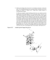 129
129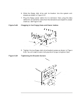 130
130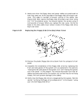 131
131 132
132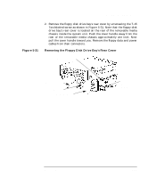 133
133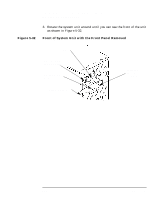 134
134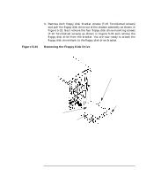 135
135 136
136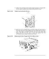 137
137 138
138

