HP dx2480 Hardware Reference Guide: HP Compaq dx2480 Business Desktop MIcrotow - Page 41
HP dx2480 - Microtower PC Manual
 |
View all HP dx2480 manuals
Add to My Manuals
Save this manual to your list of manuals |
Page 41 highlights
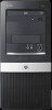
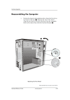
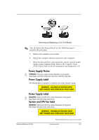
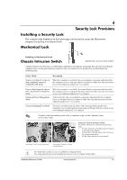
4 Security Lock Provisions Installing a Security Lock The security locks displayed on the below page can be used to secure the Microtower computer by putting a mechanical lock Mechanical Lock Installing a Mechanical Lock Chassis Intrusion Switch Photos depicted may vary as per actual machine Chassis Intrusion (CI) Switch, is a combination of hardware and software technology that can alert you when the computer cover or side panel has been removed. There are various levels of protection, as described in the following table. Status /Mode Description System switched off and power When the computer is restarted, the screen displays a message indicating that plug completely removed, the computer cover or side panel has been removed. Make sure that any system completely OFF mode access was authorized and press F1 to continue Power cable plugged in (power ON) , but System in Shutdown Mode System in Power Management Mode When the computer is restarted, the screen displays a message indicating that the computer cover or side panel has been removed. Make sure that any system access was authorized and press F1 to continue At the next boot, the screen displays a message indicating that the computer cover or side panel has been removed. Make sure that any system access was authorized and press F1 to continue System in Running/User Mode The user is notified at the next boot with a message indicating that the computer cover or side panel has been removed. Ensure that any system access was authorized and press F1 to continue ! To achieve this functionality please refer to computer setup, see the Computer Setup (F10) Utility Guide. Setting the Chassis Intrusion Switch To set the CI Protection, complete the following steps: 1. Fix the CI Switch on the Back panel of Chassis as directed in the diagram. 2. Connect the CI Switch cable to the CI Pins on the system motherboard. 3. Fix the Side panel/cover on the chassis. Installing CI switch at the back panel Connecting CI switch to CI pins on motherboard For maximum security, be sure to establish a setup password. ! The setup password prevents unauthorized access to the Computer Setup utility Hardware Reference Guide www.hp.com/in 4-1
-
 1
1 -
2
-
3
-
4
-
5
-
6
-
7
-
8
-
9
-
10
-
11
-
12
-
13
-
14
-
15
-
16
-
17
-
18
-
19
-
20
-
21
-
22
-
23
-
24
-
25
-
26
-
27
-
28
-
29
-
30
-
31
-
32
-
33
-
34
-
35
-
 36
36 -
 37
37 -
 38
38 -
 39
39 -
 40
40 -
 41
41 -
 42
42 -
 43
43 -
 44
44 -
 45
45 -
 46
46 -
47
-
48
-
49
-
50
-
51
-
52
-
53
-
54
-
55
-
56
-
57
-
58
-
59
-
60
-
61
-
62
-
63
-
64
-
65
-
66
-
67
-
68
-
69
-
70
-
71
-
72
-
73
-
74
-
75
-
76
-
77
-
78
-
79
-
80
-
81
 |
 |
