HP nx6315 HP Compaq nx6315, nx6325 Notebook PC - Maintenance and Service Guide - Page 139
Remove the two HM5.0×9.0 screw locks on each side of
 |
View all HP nx6315 manuals
Add to My Manuals
Save this manual to your list of manuals |
Page 139 highlights
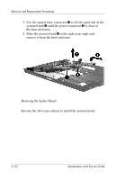
Removal and Replacement Procedures d. Switch cover (Section 5.16) e. Display assembly (Section 5.17) f. Top cover (Section 5.18) g. Speaker (Section 5.19) h. Microphone (Section 5.20) i. USB/audio board (Section 5.22) 2. Remove the two HM5.0×9.0 screw locks on each side of the external monitor connector. Removing the System Board Screw Locks Maintenance and Service Guide 5-49
-
 1
1 -
2
-
3
-
4
-
5
-
6
-
7
-
8
-
9
-
10
-
11
-
12
-
13
-
14
-
15
-
16
-
17
-
18
-
19
-
20
-
21
-
22
-
23
-
24
-
25
-
26
-
27
-
28
-
29
-
30
-
31
-
32
-
33
-
34
-
35
-
36
-
37
-
38
-
39
-
40
-
41
-
42
-
43
-
44
-
45
-
46
-
47
-
48
-
49
-
50
-
51
-
52
-
53
-
54
-
55
-
56
-
57
-
58
-
59
-
60
-
61
-
62
-
63
-
64
-
65
-
66
-
67
-
68
-
69
-
70
-
71
-
72
-
73
-
74
-
75
-
76
-
77
-
78
-
79
-
80
-
81
-
82
-
83
-
84
-
85
-
86
-
87
-
88
-
89
-
90
-
91
-
92
-
93
-
94
-
95
-
96
-
97
-
98
-
99
-
100
-
101
-
102
-
103
-
104
-
105
-
106
-
107
-
108
-
109
-
110
-
111
-
112
-
113
-
114
-
115
-
116
-
117
-
118
-
119
-
120
-
121
-
122
-
123
-
124
-
125
-
126
-
127
-
128
-
129
-
130
-
131
-
132
-
133
-
 134
134 -
 135
135 -
 136
136 -
 137
137 -
 138
138 -
 139
139 -
 140
140 -
 141
141 -
 142
142 -
 143
143 -
 144
144 -
145
-
146
-
147
-
148
-
149
-
150
-
151
-
152
-
153
-
154
-
155
-
156
-
157
-
158
-
159
-
160
-
161
-
162
-
163
-
164
-
165
-
166
-
167
-
168
-
169
-
170
-
171
-
172
-
173
-
174
-
175
-
176
-
177
-
178
-
179
-
180
-
181
-
182
-
183
-
184
-
185
-
186
-
187
-
188
-
189
-
190
-
191
-
192
-
193
-
194
-
195
-
196
-
197
-
198
-
199
-
200
-
201
-
202
-
203
-
204
-
205
-
206
-
207
-
208
-
209
-
210
-
211
 |
 |

Removal and Replacement Procedures
Maintenance and Service Guide
5–49
d.
Switch cover (
Section 5.16
)
e.
Display assembly (
Section 5.17
)
f.
Top cover (
Section 5.18
)
g.
Speaker (
Section 5.19
)
h.
Microphone (
Section 5.20
)
i.
USB/audio board (
Section 5.22
)
2. Remove the two HM5.0×9.0 screw locks on each side of the
external monitor connector.
Removing the System Board Screw Locks