HP rp8400 Site Preparation Guide, Second Edition - HP rp8400 Server Series - Page 35
Raised Floor “High Frequency Noise” Grounding, Raised Floor Metal Strip Ground System
 |
View all HP rp8400 manuals
Add to My Manuals
Save this manual to your list of manuals |
Page 35 highlights
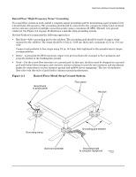
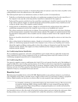
Electrical and Environmental Guidelines Electrical Factors Raised Floor "High Frequency Noise" Grounding If a raised floor system is used, install a complete signal grounding grid for maintaining equal potential over a broad band of frequencies. The grounding grid should be connected to the equipment cabinet and electrical service entrance ground at multiple connection points using a minimum #6 AWG (16mm2) wire ground conductor. See Figure 2-1 on page 19 illustrates a metallic strip grounding system. Hewlett-Packard recommends the following approaches: • Excellent-Add a grounding grid to the subfloor. The grounding grid should be made of copper strips mounted to the subfloor. The strips should be 0.032 in. (0.08 cm) thick and a minimum of 3.0 in. (8.0 cm) wide. Connect each pedestal to four strips using 1/4 in. (6.0 mm) bolts tightened to the manufacturer's torque recommendation. • Better - A grounded #6 AWG minimum copper wire grid mechanically clamped to floor pedestals and properly bonded to the building/site ground. • Good-Use the raised floor structure as a ground grid. In this case, the floor must be designed as a ground grid with bolted down stringers and corrosion resistive plating (to provide low resistance and attachment points for connection to service entrance ground and rp8400 server equipment). The use of conductive floor tiles with this style of grid further enhances ground performance. Figure 2-1 Raised Floor Metal Strip Ground System Ground wire to power panel Floor panel Hex bolt Grounding clamp Band and pedestal Chapter 2 Grounding grid element Grounding braid to computer equipment 60SP010A 11/30/99 19
-
 1
1 -
2
-
3
-
4
-
5
-
6
-
7
-
8
-
9
-
10
-
11
-
12
-
13
-
14
-
15
-
16
-
17
-
18
-
19
-
20
-
21
-
22
-
23
-
24
-
25
-
26
-
27
-
28
-
29
-
 30
30 -
 31
31 -
 32
32 -
 33
33 -
 34
34 -
 35
35 -
 36
36 -
 37
37 -
 38
38 -
 39
39 -
 40
40 -
41
-
42
-
43
-
44
-
45
-
46
-
47
-
48
-
49
-
50
-
51
-
52
-
53
-
54
-
55
-
56
-
57
-
58
-
59
-
60
-
61
-
62
-
63
-
64
-
65
-
66
-
67
-
68
-
69
-
70
-
71
-
72
-
73
-
74
-
75
-
76
-
77
-
78
-
79
-
80
 |
 |
