Hitachi 42HDT52 Owners Guide - Page 16
Connecting A Video And Stereo Audio, Source To Input1 - Input5, Connecting An S-video And Stereo
 |
View all Hitachi 42HDT52 manuals
Add to My Manuals
Save this manual to your list of manuals |
Page 16 highlights
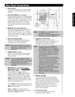
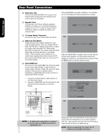
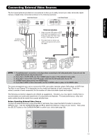
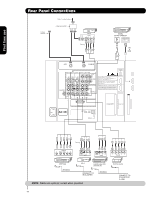
On-Screen Display The Remote Control First time use Connecting External Video Sources CONNECTING A VIDEO AND STEREO AUDIO SOURCE TO INPUT1 - INPUT5 1. Connect the cable from the VIDEO OUT of the VCR or the laserdisc player to the INPUT (VIDEO) jack, as shown on the Rear Panel on the right. 2. Connect the cable from the AUDIO OUT R of the VCR or the laserdisc player to the INPUT (AUDIO/R) jack. 3. Connect the cable from the AUDIO OUT L of the VCR or the laserdisc player to the INPUT (AUDIO/L) jack. 4. Press the INPUTS button, then select INPUT 2 from the INPUTS menu to view the program from the VCR or laserdisc player. 5. Select CABLE or AIR from the INPUTS menu to return to the last channel tuned. / G-LINK Back of R L V VCR OUTPUT VCR NOTE: 1. Completely insert the connection cord plugs when connecting to rear panel jacks. The picture and sound that is played back will be abnormal if the connection is loose. 2. A single VCR can be used for VCR #1 and VCR #2 (see page 14) but note that a VCR cannot record its own video or line output. Refer to your VCR operating guide for more information on line inputoutput connections. 3. When INPUT 3 or 4 are used, it is necessary to connect the video output of the device to the Y/VIDEO input jack of the TV. CONNECTING AN S-VIDEO AND STEREO AUDIO SOURCE TO INPUT 1, 2 AND 5 1. Connect the cable from the S-VIDEO OUT of the S-VHS VCR or the laserdisc player to the INPUT (S-VIDEO) jack, as shown on the Rear Panel on the right. 2. Connect the cable from the AUDIO OUT R of the VCR or the laserdisc player to the INPUT (AUDIO/R) jack. 3. Connect the cable from the AUDIO OUT L of the VCR or the laserdisc player to the INPUT (AUDIO/L) jack. 4. Press the INPUTS button, then select INPUT 1 from the INPUTS menu to view the program from the VCR or laserdisc player. 5. Select CABLE or AIR from the INPUTS menu to return to the last channel tuned. / G-LINK Back of VCR or R L V S-VIDEO Laserdisc Player OUTPUT VCR or Laserdisc Player NOTE: 1. Completely insert the connection cord plugs when connecting to rear panel jacks. The picture and sound that is played back will be abnormal if the connection is loose. 2. A single VCR can be used for VCR #1 and VCR #2 (see page 14), but note that a VCR cannot record its own video or line output. Refer to your VCR operating guide for more information on line inputoutput connections. 16
-
 1
1 -
2
-
3
-
4
-
5
-
6
-
7
-
8
-
9
-
10
-
 11
11 -
 12
12 -
 13
13 -
 14
14 -
 15
15 -
 16
16 -
 17
17 -
 18
18 -
 19
19 -
 20
20 -
 21
21 -
22
-
23
-
24
-
25
-
26
-
27
-
28
-
29
-
30
-
31
-
32
-
33
-
34
-
35
-
36
-
37
-
38
-
39
-
40
-
41
-
42
-
43
-
44
-
45
-
46
-
47
-
48
-
49
-
50
-
51
-
52
-
53
-
54
-
55
-
56
-
57
-
58
-
59
-
60
-
61
-
62
-
63
-
64
-
65
-
66
-
67
-
68
-
69
-
70
-
71
-
72
-
73
-
74
-
75
-
76
-
77
-
78
-
79
-
80
-
81
-
82
-
83
-
84
-
85
-
86
-
87
-
88
-
89
-
90
-
91
-
92
-
93
-
94
-
95
-
96
-
97
-
98
-
99
-
100
-
101
-
102
-
103
-
104
 |
 |
