Hitachi 55VG825 Owners Guide - Page 20
your HITACHI LCD Rear PTV Remote Control and the TV Guide On Screen system to control your cable box
 |
View all Hitachi 55VG825 manuals
Add to My Manuals
Save this manual to your list of manuals |
Page 20 highlights
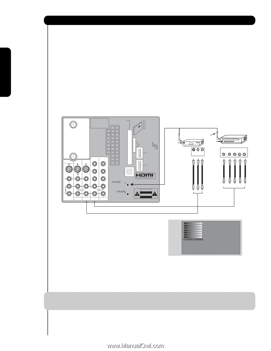
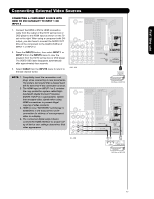
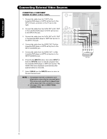
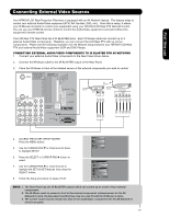
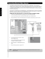
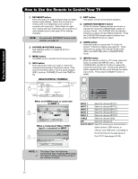
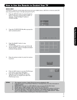
First time use Connecting External Video Sources Your HITACHI LCD Rear Projection Television is equipped with a G-LINK feature. This connection is necessary for the TV Guide On ScreenTM system to work with your cable box to receive program listings and to enable VCR recording features. Once you setup the G-LINK (IR Mouse) connector, then you can use your HITACHI LCD Rear PTV Remote Control and the TV Guide On Screen system to control your cable box and VCR recording features. The LCD Rear PTV Rear Panel has 2 IR BLASTER jacks. One IR Mouse cable can connect up to 2 external Audio/Video components. Please see the following example of a G-LINK setup between your HITACHI LCD Rear PTV and external Audio/Video equipment (VCR and Cable box). CONNECTING THE CABLE BOX/VCR TO G-LINK FOR TV GUIDE ON SCREENTM SYSTEM 1. Connect your external Audio/Video components to the Rear Panel shown below. 2. Connect the IR Mouse cable to the IR BLASTER/G-LINK output of the Rear Panel. 3. Place the IR Mouse in front of the infrared sensor of the external components you want to control. CABLE Apparatus Claims of U.S. Patent Nos. 4,631,603; 4,577,216; 4,819,098; 4,907,093; and 6,381,747 licensed for limited viewing uses only. CableCARD™ (Top of card faces right) Top faces AIR MONITOR OUT S I V I D E O V I D E O (MONO) (MONO) Y/ VIDEO PB PR (MONO) Y/ VIDEO PB PR (MONO) A L U D TV AS CENTER I O R AUDIO TO HI-FI INPUT 1 INPUT 2 INPUT 3 INPUT 4 OPTICAL OUT Digital Audio / G-LINK Upgrade Card HDMI INPUT 1 HDMI INPUT 2 CAUTION Infrared Sensor IR Mouse Infrared Sensor VCR V L R OUTPUT Cable Box OUTPUT Y PB/CB PR/CR R L 4. To access the TV Guide On-ScreenTM system, press the MENU button. 5. Use the CURSOR PAD ̄ or channel scroll down to highlight TV GUIDE ON SCREEN. 6. Press the SELECT or CURSOR PAD ̈ button to select. 7. Follow the Setup procedure on pages 47-51. Video Audio TV Guide On Screen Channel Manager Locks Timers Setup Move SEL Select NOTE: The IR Mouse must be placed in front of the external components infrared sensor for the AV Network to work. 20
-
 1
1 -
2
-
3
-
4
-
5
-
6
-
7
-
8
-
9
-
10
-
11
-
12
-
13
-
14
-
 15
15 -
 16
16 -
 17
17 -
 18
18 -
 19
19 -
 20
20 -
 21
21 -
 22
22 -
 23
23 -
 24
24 -
 25
25 -
26
-
27
-
28
-
29
-
30
-
31
-
32
-
33
-
34
-
35
-
36
-
37
-
38
-
39
-
40
-
41
-
42
-
43
-
44
-
45
-
46
-
47
-
48
-
49
-
50
-
51
-
52
-
53
-
54
-
55
-
56
-
57
-
58
-
59
-
60
-
61
-
62
-
63
-
64
-
65
-
66
-
67
-
68
-
69
-
70
-
71
-
72
-
73
-
74
-
75
-
76
-
77
-
78
-
79
-
80
-
81
-
82
-
83
-
84
-
85
-
86
-
87
-
88
-
89
-
90
-
91
-
92
-
93
-
94
-
95
-
96
-
97
-
98
-
99
-
100
-
101
-
102
-
103
-
104
 |
 |