Hitachi B13FI Instruction Manual - Page 11
Assembly And Adjustments
 |
UPC - 717709012035
View all Hitachi B13FI manuals
Add to My Manuals
Save this manual to your list of manuals |
Page 11 highlights
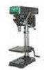
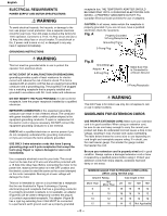
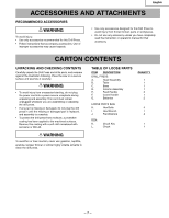
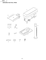
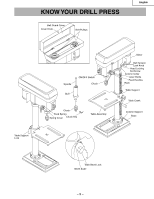
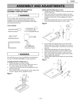
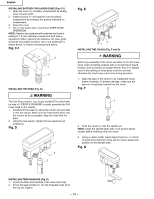
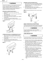
English ASSEMBLY AND ADJUSTMENTS ESTIMATED ASSEMBLY TIME 20-40 MINUTES ASSEMBLY INSTRUCTIONS WARNING For your safety, never connect plug to power source receptacle until all assembly and adjustment steps are completed, and you have read and understood the safety and operating instructions. TOOLS NEEDED INSTALLING THE TABLE (Fig. B and C) 1. Loosen set screw (1). Remove rack (2) and retaining ring (3) from column (4). 2. Place rack inside table assembly bracket (5) with large, unmachined portion of rack to the top. Slide rack into slot in bracket so that teeth of reack engage pinion gear in bracket. 3. Slide table assembly with rack over column. Place bottom end of rack inside beveled edge of column flange. Fig. B 3 1 2 5 Slotted Screwdriver 8″ & 10″ Adjustable Wrench 4 Combination Wrench Mallet Framing Square Combination Square WARNING The Drill Press is very heavy and MUST be assembled with the help of 2 PEOPLE OR MORE, to safely assemble it. COLUMN SUPPORT TO BASE (Fig. A) 1. Position the base (1) on floor or bench. 2. Place the column (2) on the base, aligning the holes in the column support with the holes in the base. 3. Locate the four long hex bolts (3) and washers (4) from the loose parts bag. 4. Place a bolt in each hole through the column support and the base. Tighten with an adjustable wrench. Fig. A 2 3 3 4 1 4. (Fig. C) Slide rack retaining ring (3) over column with beveled edge down. Position ring against top of rack so that rack is in beveled edge of ring. Secure ring with set screw (1). 5. Rotate table assembly around column. Adjust rack retaining ring as necessary to prevent binding of rack. 6. Attach crank handle (6) to shaft (7), rotate to remove slack, and shoulder crank handle against table bracket. Secure handle with screw (8). 7. Tighten table bracket locking handle (9) to secure table assembly. Fig. C 9 3 7 8 6 - 11 -
-
 1
1 -
2
-
3
-
4
-
5
-
 6
6 -
 7
7 -
 8
8 -
 9
9 -
 10
10 -
 11
11 -
 12
12 -
 13
13 -
 14
14 -
 15
15 -
 16
16 -
17
-
18
-
19
-
20
-
21
-
22
-
23
-
24
-
25
-
26
-
27
-
28
-
29
-
30
-
31
-
32
-
33
-
34
-
35
-
36
-
37
-
38
-
39
-
40
-
41
-
42
-
43
-
44
-
45
-
46
-
47
-
48
-
49
-
50
-
51
-
52
-
53
-
54
-
55
-
56
 |
 |