Hitachi C10RA3 Instruction Manual - Page 12
Warning - replacement parts
 |
UPC - 717709011038
View all Hitachi C10RA3 manuals
Add to My Manuals
Save this manual to your list of manuals |
Page 12 highlights
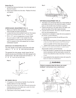
English 4. Remove the arbor nut (5) and outer flange (6). (Fig. E) 5. Install the saw blade onto the arbor with the blade teeth pointing toward the front of the saw. 6. Install the flange (6) against the blade and thread the arbor nut (5) as far as possible by hand. Ensure that the blade is flush againstthe inner side of the blade flange. WARNING To avoid possible injury and damage to the workpiece, be sure to install the blade with the teeth pointing toward the front of table in the direction of the rotation arrow on the blade guard. Fig. E 47 6 5 7. To tighten the arbor nut (5), place the open-end wrench (8) on the flats of the saw arbor to keep the arbor from turning. (Fig. F) 8. Place the box-end wrench (9) on the arbor nut (5), and turn clockwise (to the rear of the table). 9. Replace the blade insert in the table recess, insert the screws through the front and rear hole and tighten remembering the rubber washer under the rear of the insert and leveling the rear of the insert to the table. Fig. F 9 8 5 WARNING To avoid injury from a thrown workpiece, blade parts, or blade contact, never operate saw without the proper insert in place. Use the original installed insert for all throught sawing operations except dado cuts. A special dado insert plate must be installed when using a dado blade. BLADE GUARD ASSEMBLY (FIG. G, H, I ) 1. Set the blade to maximum height and the tilt to zero degrees on the bevel scale with the hand wheels. Lock the blade bevel lock knob. 2. Place the spring washer (2), flat washer (3), external tooth lock washer (4) onto the blade guard mounting bolt (1-Fig. G). 3. Insert bolt and washer assembly through splitter bracket (5). Fig. G Blade guard splitter 54 2 1 3 12 11 4. Install the blade guard splitter & bracket assembly into the rear of the saw table. Thread the bolt (1) into the internally threaded pivot rod (7-Fig. H) until snug. NOTE: The blade guard and splitter is removed from the illustration for clarity. Fig. H 7 6. Lift blade guard arm (8) up and using a straight edge, align the blade guard splitter (9) with the saw blade (10). (Fig. I) 7. Shift the splitter bracket assembly to right or left until parallel alignment to the blade is achieved. 8. When the splitter is properly aligned with the saw blade, tighten the bolt securely. NOTE: The splitter bracket must always be correctly aligned so the cut workpiece will pass on either side without binding or twisting. WARNING See Fig. G flat washers (11) must be under bolts (12). NOTE: Be sure to tighten nuts very tight and periodically check tightness. - 12 -
-
 1
1 -
2
-
3
-
4
-
5
-
6
-
 7
7 -
 8
8 -
 9
9 -
 10
10 -
 11
11 -
 12
12 -
 13
13 -
 14
14 -
 15
15 -
 16
16 -
 17
17 -
18
-
19
-
20
-
21
-
22
-
23
-
24
-
25
-
26
-
27
-
28
-
29
-
30
-
31
-
32
-
33
-
34
-
35
-
36
-
37
-
38
-
39
-
40
-
41
-
42
-
43
-
44
-
45
-
46
-
47
-
48
-
49
-
50
-
51
-
52
-
53
-
54
-
55
-
56
-
57
-
58
-
59
-
60
-
61
-
62
-
63
-
64
-
65
-
66
-
67
-
68
-
69
-
70
-
71
-
72
 |
 |
