Hitachi C10RA3 Instruction Manual - Page 16
Mount the cover on the table to fix the pointer. - blade wrench
 |
UPC - 717709011038
View all Hitachi C10RA3 manuals
Add to My Manuals
Save this manual to your list of manuals |
Page 16 highlights
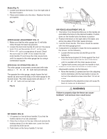
English RIP FENCE INDICATOR (FIG. T) NOTE: The rip fence indicator points to the scale on the front of the table saw. Measurement shown by the indicator will provide the user with accuracy up to 1/16 of an inch. Measurement shown is the distance from the blade to the side of the fence closest to the blade. 1. To check the accuracy, measure the actual distance (1) to the side of the rip fence. If there is a difference between the measurement and the indicator, adjust the indicator as shown next. 2. Loosen the indicator screw (2). Slide the indicator to the correct measurement position on the scale, then retighten the screw (2). Fig. T ADJUSTING THE CUTTING LINE INDICATOR (FIG. U) 1. Take off the cover (1) by loosening screws (2). 2. Adjust the pointer (3) to align to the blade. 3. Mount the cover on the table to fix the pointer. NOTE: The pointer was set up to align to the right side of the blade when packing. Fig. U 13 1 3 2 1 2 TABLE EXTENSION SCALE POINTER (FIG. T-1) The table extension scale pointer (1) should be at 13.5 inches on the scale when the extension is in the closed position. If not, loosen the holding screw (2), position the pointer over 13.5 inches and re-tighten the screw. Fig. T-1 ADJUSTING CAM LOCKING LEVER (FIG. V) If the extension table moves when it is open and locked, then the cam locking lever (1) may be loose and need adjustment, therefore, adjustment to the cam locking lever is necessary. To adjust the locking lever tension, turn the bar (2) with a 10 mm wrench until it is tightened, but do not over tighten. Fig. V 1 2 1 2 - 16 -
-
 1
1 -
2
-
3
-
4
-
5
-
6
-
7
-
8
-
9
-
10
-
 11
11 -
 12
12 -
 13
13 -
 14
14 -
 15
15 -
 16
16 -
 17
17 -
 18
18 -
 19
19 -
 20
20 -
 21
21 -
22
-
23
-
24
-
25
-
26
-
27
-
28
-
29
-
30
-
31
-
32
-
33
-
34
-
35
-
36
-
37
-
38
-
39
-
40
-
41
-
42
-
43
-
44
-
45
-
46
-
47
-
48
-
49
-
50
-
51
-
52
-
53
-
54
-
55
-
56
-
57
-
58
-
59
-
60
-
61
-
62
-
63
-
64
-
65
-
66
-
67
-
68
-
69
-
70
-
71
-
72
 |
 |
