Hitachi DH30PC2 Instruction Manual - Page 9
Functional Description - instructions
 |
UPC - 717709011113
View all Hitachi DH30PC2 manuals
Add to My Manuals
Save this manual to your list of manuals |
Page 9 highlights
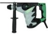
English FUNCTIONAL DESCRIPTION NOTE: The information contained in this Instruction Manual is designed to assist you in the safe operation and maintenance of the power tool. NEVER operate, or attempt any maintenance on the tool unless you have first read and understood all safety instructions contained in this manual. Some illustrations in this Instruction Manual may show details or attachments that differ from those on your own power tool. NAME OF PARTS Drill bit Stopper Nameplate Change lever Trigger Grip Handle SPECIFICATIONS Side handle Housing Brush cap (inside the tail cover) Set screw (under the tail cover) Tail cover Fig. 1 Motor Power Source Current Capacity No-Load Speed Full-load Impact Rate Weight Single-Phase, Series Commutator Motor Single-Phase, 120V 60Hz 7.4A Concrete: 5/32" - 1-3/16" (4mm - 30mm) Steel: Wood: 1/2" (13mm) 1-1/4" (32mm) 0 - 850/min. 0 - 3,700/min. 9.5 lbs (4.3 kg) 9
-
 1
1 -
2
-
3
-
 4
4 -
 5
5 -
 6
6 -
 7
7 -
 8
8 -
 9
9 -
 10
10 -
 11
11 -
 12
12 -
 13
13 -
 14
14 -
15
-
16
-
17
-
18
-
19
-
20
-
21
-
22
-
23
-
24
-
25
-
26
-
27
-
28
-
29
-
30
-
31
-
32
-
33
-
34
-
35
-
36
-
37
-
38
-
39
-
40
-
41
-
42
-
43
-
44
-
45
-
46
-
47
-
48
-
49
-
50
-
51
-
52
-
53
-
54
-
55
-
56
-
57
-
58
-
59
-
60
-
61
-
62
-
63
-
64
-
65
-
66
-
67
-
68
-
69
-
70
-
71
-
72
-
73
-
74
-
75
-
76
 |
 |
