Hitachi DK23EA Specifications - Page 38
Identify Device [ECh] - firmware
 |
View all Hitachi DK23EA manuals
Add to My Manuals
Save this manual to your list of manuals |
Page 38 highlights
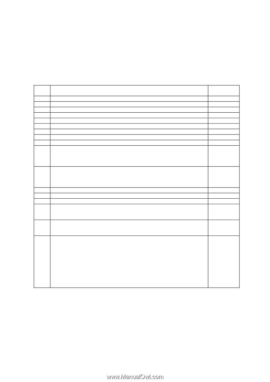
6.3.2.3.1 Identify Device [ECh] The Identify Device command enables the host to receive parameter information from the device. When the command is issued, the device sets BSY, stores the required parameter information in the sector buffer, sets DRQ, and generates an interrupt. The host then reads the information from the sector buffer through the Data Register. The parameter words are defined in Table 6.5 and 6.6. All reserved bits or words shall be zero. Table 6.5 Identify Device Information Word Description 0 General configuration 1 Number of logical cylinders 2 Specific configuration 3 Number of logical heads 4 Number of unformatted bytes per track 5 Number of unformatted bytes per sector 6 Number of logical sectors per logical track 7-9 Vendor specific 10-19 Serial number (20 ASCII characters) 20 Buffer type 0000h = Not specified 0001h = Single port single buffer 0002h = Dual port multi-sector buffer 0003h = Dual port multi-sector buffer with read caching capability 21 Buffer size in 512 byte increments (0000h=not specified) 22 Number of ECC bytes passed on READ/WRITE LONG commands 23-26 Firmware revision(8 ASCII Characters) 27-46 Model number(40 ASCII Characters) 47 Number of sectors on multiple commands Bit 15 - 8 80h (fixed) Bit 7 - 0 Number of sectors on multiple command 48 Double word I/O not supported 0000h = cannot perform double word I/O 0001h = can perform double word I/O 49 Capabilities Bit 15 - 14 0 = Reserved Bit 13 1 = Standby timer values as specified in ATA-2 specification supported Bit 12 0 = Reserved Bit 11 1 = IORDY supported Bit 10 1 = IORDY can be disabled Bit 9 1 = LBA supported Bit 8 1 = DMA supported Bit 7 - 0 Vendor Specific Value (HEX.) 045Ah See table 6.6 C837h See table 6.6 See table 6.6 0003h DK23CA-15/ 75: 0400h DK23CA-30F/ 30: 1000h 0004h 8010h 0000h 0B00h K6602637 Rev.3 02.27.01 - 38 -
-
 1
1 -
2
-
3
-
4
-
5
-
6
-
7
-
8
-
9
-
10
-
11
-
12
-
13
-
14
-
15
-
16
-
17
-
18
-
19
-
20
-
21
-
22
-
23
-
24
-
25
-
26
-
27
-
28
-
29
-
30
-
31
-
32
-
 33
33 -
 34
34 -
 35
35 -
 36
36 -
 37
37 -
 38
38 -
 39
39 -
 40
40 -
 41
41 -
 42
42 -
 43
43 -
44
-
45
-
46
-
47
-
48
-
49
-
50
-
51
-
52
-
53
-
54
-
55
-
56
-
57
-
58
-
59
-
60
-
61
-
62
-
63
-
64
-
65
-
66
-
67
-
68
-
69
-
70
-
71
-
72
-
73
-
74
-
75
-
76
-
77
-
78
-
79
-
80
-
81
-
82
-
83
-
84
-
85
-
86
-
87
-
88
-
89
-
90
-
91
-
92
-
93
-
94
-
95
-
96
-
97
-
98
-
99
-
100
-
101
-
102
-
103
-
104
 |
 |