Hitachi DK23EA Specifications - Page 49
Set Multiple Mode [C6h], 3.2.5.7 Execute device diagnostic [90h]
 |
View all Hitachi DK23EA manuals
Add to My Manuals
Save this manual to your list of manuals |
Page 49 highlights
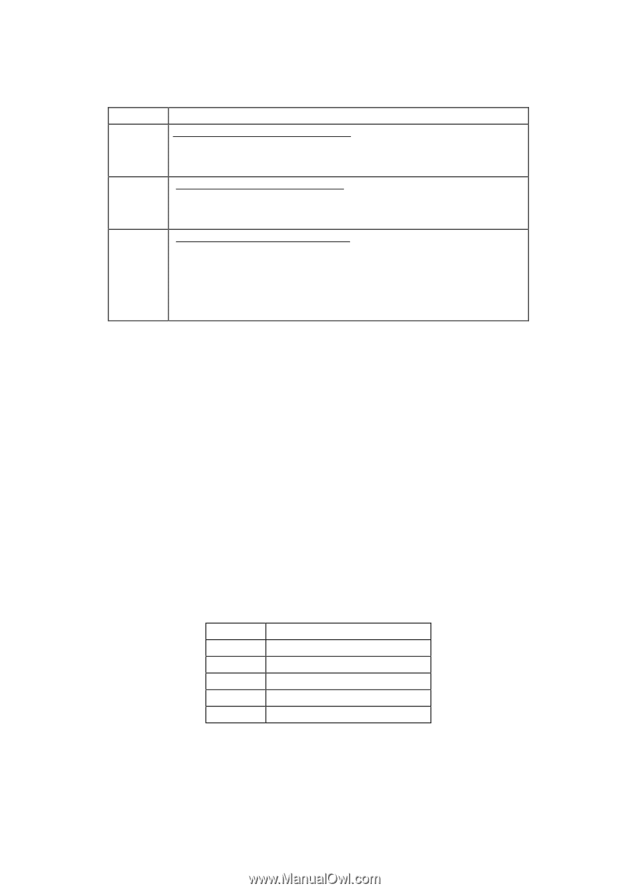
Table 6.8 Transfer mode code definition SC Transfer Mode 1Xh Single Word DMA Mode (X: 0, 1, 2): Mode 0: 2.0 MB/sec Mode 1: 4.1 MB/sec Mode 2: 8.3 MB/sec 2Xh Multi-Word DMA Mode (X: 0, 1, 2): Mode 0: 4.1 MB/sec Mode 1: 13.3 MB/sec Mode 2: 16.6 MB/sec 4Xh Ultra DMA Mode (X: 0, 1, 2, 3, 4, 5): Mode 0: 16.6 MB/sec Mode 1: 25.0 MB/sec Mode 2: 33.3 MB/sec Mode 3: 44.4 MB/sec Mode 4: 66.6 MB/sec Mode 5: 100.0 MB/sec SC = Sector Count Register 6.3.2.5.6 Set Multiple Mode [C6h] This command allows the device to specify the number of sectors per block to perform Read Multiple and Write Multiple operations. The Sector Count Register is loaded with the number of sectors per block. Block sizes of 2, 4, 8, and 16 sectors are supported. Upon receipt of the command, the device sets BSY=1 and checks the Sector Count Register. If the Sector Count Register contains a valid value, then the value is loaded for all subsequent Multiple commands and execution of those commands is enabled. If an invalid value is specified, an Aborted Command error is posted and execution of the Multiple commands is disabled. The Multiple commands cannot be executed in the default mode at power on or after a hardware reset. 6.3.2.5.7 Execute device diagnostic [90h] This command allows the device to perform a self-diagnostics. When DRV0 and DRV1 are connected in the daisy chain mode, this command is executed for both of the devices. When the device receives this command, it sets BSY=1 and executes the self-diagnostic operation. Then the device registers the diagnostic result in the Error register, clears BSY, and generates an interrupt. Table 6.9 Diagnostic Codes Code Contents 01 No Error 02 Controller error 03 Sector buffer error 05 CPU error 8X DRV1 error K6602637 Rev.3 02.27.01 - 49 -
-
 1
1 -
2
-
3
-
4
-
5
-
6
-
7
-
8
-
9
-
10
-
11
-
12
-
13
-
14
-
15
-
16
-
17
-
18
-
19
-
20
-
21
-
22
-
23
-
24
-
25
-
26
-
27
-
28
-
29
-
30
-
31
-
32
-
33
-
34
-
35
-
36
-
37
-
38
-
39
-
40
-
41
-
42
-
43
-
 44
44 -
 45
45 -
 46
46 -
 47
47 -
 48
48 -
 49
49 -
 50
50 -
 51
51 -
 52
52 -
 53
53 -
 54
54 -
55
-
56
-
57
-
58
-
59
-
60
-
61
-
62
-
63
-
64
-
65
-
66
-
67
-
68
-
69
-
70
-
71
-
72
-
73
-
74
-
75
-
76
-
77
-
78
-
79
-
80
-
81
-
82
-
83
-
84
-
85
-
86
-
87
-
88
-
89
-
90
-
91
-
92
-
93
-
94
-
95
-
96
-
97
-
98
-
99
-
100
-
101
-
102
-
103
-
104
 |
 |