Hitachi EC119SA Instruction Manual - Page 7
Operation And Maintenance - compressor
 |
UPC - 717709011243
View all Hitachi EC119SA manuals
Add to My Manuals
Save this manual to your list of manuals |
Page 7 highlights
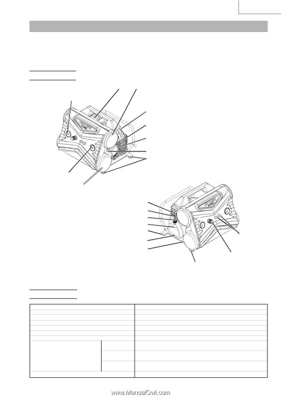
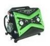
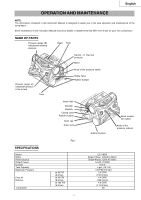
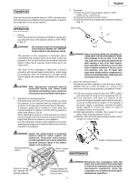
English OPERATION AND MAINTENANCE NOTE: The information contained in this Instruction Manual is designed to assist you in the safe operation and maintenance of the compressor. Some illustrations in this Instruction Manual may show details or attachments that differ from those on your own compressor. NAME OF PARTS Pressure gauge (B) indicates the working pressure Head Tank Switch of thermal protecter Motor Pressure gauge (A) indicates the pressure in the air tank Tank Knob of the pressure switch Safety valve Rubber bumper Intake filter Cylinder Dipstick Casing cover Rubber bumper Drain cap Drain cock Rubber bumper Quick coupler (air outlet) Knob of the pressure reducer SPECIFICATIONS Model Motor Power Source Output Power Current Tank Capacity Maximum Pressure Free Air Delivery Lubrication Fig.1 at 40 PSI (2.8 bar) at 90 PSI (6.2 bar) at 100 PSI (6.9 bar) EC119SA Single-Phase, Induction Motor Single-Phase, 120V AC 60Hz 1.6 HP (1.2KW) 15.0 A 4 gal. (15.1 ltr) 135 PSI (9.3 bar) 5.3 CFM (150 ltr/min) 4.4 CFM (125 ltr/min) 4.0 CFM (113 ltr/min) Oil - 7 -
-
 1
1 -
 2
2 -
 3
3 -
 4
4 -
 5
5 -
 6
6 -
 7
7 -
 8
8 -
 9
9 -
 10
10 -
 11
11 -
 12
12 -
13
-
14
-
15
-
16
-
17
-
18
-
19
-
20
-
21
-
22
-
23
-
24
-
25
-
26
-
27
-
28
-
29
-
30
-
31
-
32
 |
 |