Hitachi EC119SA Instruction Manual - Page 8
English, Accessory, Applications, Prior To Operation - repair
 |
UPC - 717709011243
View all Hitachi EC119SA manuals
Add to My Manuals
Save this manual to your list of manuals |
Page 8 highlights
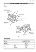
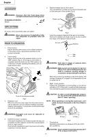
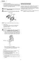
English ACCESSORY 5. Dipstick insertion and oil level check Use a screwdriver or similar tool to remove the plastic cap on the lower part of the cylinder (Fig.3). WARNING: Accessory other than these shown below can lead to malfunction and resulting injuries. STANDARD ACCESSORY Dipstick 1 Plastic cap Cylinder APPLICATIONS Air source of the pneumatic nailer and stapler. WARNING: Never use compressor for applications other than compressor for pneumatic nailer and stapler. Fig.3 Insert the accessory dipstick all the way to the bottom. Remove the dipstick and make sure the oil level is within the range of the dipstick notches (Fig.4). PRIOR TO OPERATION 1. Power source Ensure that the power source to be utilized conforms to the power source requirements specified on the product nameplate. 2. Power switch Ensure that the knob of the pressure switch is in the "OFF" position (Fig. 2). If the plug is connected to a receptacle while the knob is in the "ON" position, the compressor will start operating immediately and can cause serious injury. ON OFF Air vent Dipstick Max Min Fig.4 WARNING: Drain tank to release air pressure before removing the dipstick. WARNING: Make sure air vent in dipstick is free from debris. If air vent is blocked pressure can build in crankcase causing damage to compressor and possible personal injury. When the oil volume is insufficient, refer to the section "Oil change-oil topping off" on page 10 for a description of how to supply the oil. 6. Right running position Position the compressor on a flat surface or one with an inclination of 10° at the most, in a well ventilated area away from atmospheric agents and not in explosive areas (Fig.5). Knob of the pressure switch Fig.2 3. Extension cord When the work area is far away from the power source, use an extension cord of sufficient thickness and rated capacity (refer page 6). The extension cord should be kept as short as practicable. CAUTION : In order to avoid damaging the compressor, do not allow the unit to be tilted more than 10° when operating. NOTE: When operating or storing the copmressor, set 4 rubber bumpers downward on the floor (Refer to Fig.1) WARNING: Damaged cord must be replaced or repaired. 4. Confirm the power receptacle If the power receptacle only loosely accepts the plug, the receptacle must be repaired. Contact the nearest electric store for repair service. If such a faulty receptacle is used, may cause overheating, resulting in a serious hazard. 10°max 10°max Fig.5 7. Temperature Operating temperatures are between 32°F and 104°F (0°C and 40°C). CAUTION: Never operate in temperatures below 32°F (0°C) or above 104°F (40°C). - 8 -
-
 1
1 -
2
-
 3
3 -
 4
4 -
 5
5 -
 6
6 -
 7
7 -
 8
8 -
 9
9 -
 10
10 -
 11
11 -
 12
12 -
 13
13 -
14
-
15
-
16
-
17
-
18
-
19
-
20
-
21
-
22
-
23
-
24
-
25
-
26
-
27
-
28
-
29
-
30
-
31
-
32
 |
 |