Hitachi c10fs Instruction Manual - Page 19
Warning, Caution - compound miter saw
 |
View all Hitachi c10fs manuals
Add to My Manuals
Save this manual to your list of manuals |
Page 19 highlights
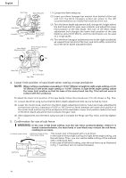
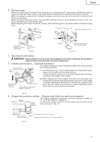
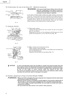
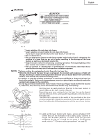
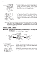
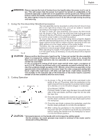
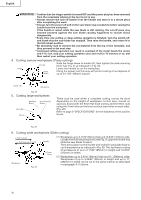
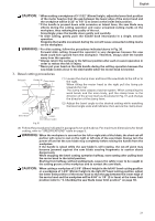
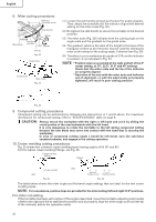
English WARNING: Always remove the lock-off button from the handle when the power tool is not in use. This will ensure that the power tool cannot be turned on accidentally or by someone (especially a child) who is not qualified to use the power tool. If the lock-off button is left in the handle, serious personal injury can result. Since the lock-off button fits rather tightly, it may be necessary to turn it to the left and right during mounting and removing. 2. Using the Vise Assembly (Standard accessory) Screw Holder The vise assembly can be mounted on either the left fence (Fence (B)) or the right fence (Fence (A)), and can be raised or lowered 6mm Knob Bolt Knob according to the height of the workpiece. To raise or lower the vise assembly, first loosen the 6mm knob V-Groove bolt. As shown in Fig. 26, the vise shaft has three locking grooves Vise Plate into which the tip of the 6mm wing bolt is designed to fit in order to lock the screw holder in the desired position. Groove To ensure that the tip of the 6mm wing bolt is properly aligned with the desired locking groove on the vise shaft, simply align the Workpiece upper surface of the fence to either of three v-grooves on the vise Fence shaft surface or to the lower surface of the screw holder. Therefore, the vise assembly can be attached in either of three positions to ensure proper height adjustment. 6mm Knob Bolt Fig. 26 After adjusting the height, firmly tighten the 6mm wing bolt; then turn the upper knob, as necessary, to securely attach the workpiece in position. CAUTION: Always confirm that the motor head (see Fig. 1) does not contact the vise assembly when it is lowered for cutting. If there is any danger that it may do so, loosen the 8mm knob bolt slightly and move the vise assembly to a position where it will not contact the saw blade. In case of compound cutting of left bevel angle and left miter angle, a workpiece of up to 2-3/16" (55mm) can be fixed with a vise assembly mounted on the left side. In case the workpiece height exceeds 2-3/16" (55mm), mount the ivse assembly on the opposite side of the inclination of the motor head. For other compound cutting (left bevel + right miter, right bevel + left miter and right bevel + right miter), mount the vise asembly on the opposite side of the inclination of the motor head to avoid the contact of the vise assembly with the motor head. 3. Cutting Operation a Adjusting Line b (1) As shown in Fig. 27 the width of the saw blade is the width of the cut. Therefore, slide the workpiece to the right (viewed from the operator's position) when length b is desired, or to the left when length a is desired. (Only Model C10FSH) If a laser marker is used, align the laser line with the left side of the saw blade, and then align the ink line with the laser line. a b Marking a (pre-marked) b Marking (pre-marked) (Front View) Fig. 27 (2) Once the saw blade reaches maximum speed, push the handle down carefully until the saw blade approaches the workpiece. (3) Once the saw blade contacts the workpiece, push the handle down gradually to cut into the workpiece. (4) After cutting the workpiece to the desired depth, turn the power tool OFF and let the saw blade stop completely before raising the handle from the workpiece to return it to the full retract position. CAUTION: * Increased pressure on the handle will not increase the cutting speed. On the contrary, too much pressure may result in overload of the motor and/or decreased cutting efficiency. 19
-
 1
1 -
2
-
3
-
4
-
5
-
6
-
7
-
8
-
9
-
10
-
11
-
12
-
13
-
 14
14 -
 15
15 -
 16
16 -
 17
17 -
 18
18 -
 19
19 -
 20
20 -
 21
21 -
 22
22 -
 23
23 -
 24
24 -
25
-
26
-
27
-
28
-
29
-
30
-
31
-
32
-
33
-
34
-
35
-
36
-
37
-
38
-
39
-
40
-
41
-
42
-
43
-
44
-
45
-
46
-
47
-
48
-
49
-
50
-
51
-
52
-
53
-
54
-
55
-
56
-
57
-
58
-
59
-
60
-
61
-
62
-
63
-
64
-
65
-
66
-
67
-
68
-
69
-
70
-
71
-
72
-
73
-
74
-
75
-
76
-
77
-
78
-
79
-
80
-
81
-
82
-
83
-
84
-
85
-
86
-
87
-
88
-
89
-
90
-
91
-
92
-
93
-
94
-
95
-
96
 |
 |
