Hitachi c10fs Instruction Manual - Page 22
Miter cutting procedures, Compound cutting procedures, Crown molding cutting procedures, For miter - sliding compound miter saw
 |
View all Hitachi c10fs manuals
Add to My Manuals
Save this manual to your list of manuals |
Page 22 highlights
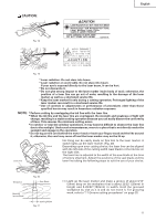
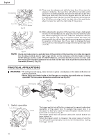
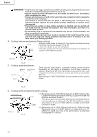
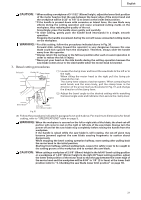
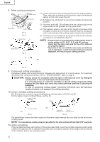
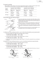
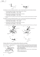
English 8. Miter cutting procedures Indicator (For miter scale) Side Handle Turntable Turn the Miter Scale turntable Tighten Lever Loosen Pull up Fig. 32 Angle Scale a Grade Scale Miter Scale Fig. 33 (1) Loosen the side handle and pull up the lever for angle stoppers. Then, adjust the turntable until the indicator aligns with desired setting on the miter scale (Fig. 32). (2) Re-tighten the side handle to secure the turntable in the desired position. (3) The miter scale (Fig. 33) indicates both the cutting angle on the angle scale and the gradient on the grade scale. (4) The gradient, which is the ratio of the height to the base of the triangular section to be removed, may be used for setting the miter scale instead of the cutting angle, if desired (see Fig. 33). (5) Therefore, to cut a workpiece at a grade of 2/10, set the indicator to position a as indicated in Fig. 33. NOTE: * Positive stops are provided at the right and left of the 0° center setting, at 15°, 22.5°, 31.6° and 45° settings. Check that the miter scale and the tip of the indicator are properly aligned. * Operation of the saw with the miter scale and indicator out of alignment, or with the side handle not properly tightened, will result in poor cutting precision. Fig. 34 9. Compound cutting procedures Compound cutting can be performed by following the instructions in 7 and 8 above. For maximum dimensions for compound cutting, refer to "SPECIFICATIONS" table on page 9. CAUTION: Always secure the workpiece with the right or left hand and cut it by sliding the round portion of the saw backwards with the left hand. It is very dangerous to rotate the turntable to the left during compound cutting because the saw blade may come into contact with the hand that is securing the workpiece. In case of compound cutting (angle + bevel) by left bevel, turn the sub-fence counterclockwise, and engage in the cutting operation. 10. Crown molding cutting procedures Fig. 35 shows two common crown molding types having angles of (θ) 38° and 45°. For the typical crown molding fittings, see Fig. 36. A upper surface Ceiling Ceiling Wall B lower surface Wall 12 Inside corner 34 Outside corner Fig. 35 Fig. 36 The table below shows the miter angle and the bevel angle settings that are ideal for the two crown molding types. NOTE: For convenience, positive stops are provided for the miter setting (left and right 31.6°) positions. For miter cut setting If the turntable has been set to either of the angles described, move the turntable adjusting side handle a little to the right and left to stabilize the position and to properly align the miter angle scale and the tip of the indicator before the operation starts. 22
-
 1
1 -
2
-
3
-
4
-
5
-
6
-
7
-
8
-
9
-
10
-
11
-
12
-
13
-
14
-
15
-
16
-
 17
17 -
 18
18 -
 19
19 -
 20
20 -
 21
21 -
 22
22 -
 23
23 -
 24
24 -
 25
25 -
 26
26 -
 27
27 -
28
-
29
-
30
-
31
-
32
-
33
-
34
-
35
-
36
-
37
-
38
-
39
-
40
-
41
-
42
-
43
-
44
-
45
-
46
-
47
-
48
-
49
-
50
-
51
-
52
-
53
-
54
-
55
-
56
-
57
-
58
-
59
-
60
-
61
-
62
-
63
-
64
-
65
-
66
-
67
-
68
-
69
-
70
-
71
-
72
-
73
-
74
-
75
-
76
-
77
-
78
-
79
-
80
-
81
-
82
-
83
-
84
-
85
-
86
-
87
-
88
-
89
-
90
-
91
-
92
-
93
-
94
-
95
-
96
 |
 |
