Honeywell 5890PI Installation Instructions - Page 2
Horizontal Adjustment of Lens - install
 |
View all Honeywell 5890PI manuals
Add to My Manuals
Save this manual to your list of manuals |
Page 2 highlights
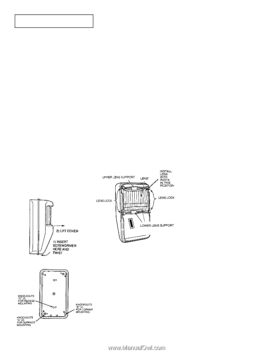
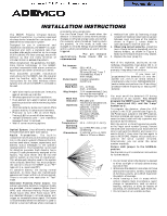
INSTALLATION IMPORTANT: For installation with pets, be sure to follow the guidelines described in Table 2. Radio Transmission Path Check Verify that a strong transmission path between the 5890PI and the system's Receiver/Control exists before permanently mounting the detector. Do this by performing the Walk-Test (described later) with the detector temporarily mounted in its proposed location. The 5890PI will transmit when sensing motion (waving an arm or walking into an area). Sometimes, moving the detector only a few centimeters means the difference between a strong and weak transmission path. Experiment until you are satisfied that the location provides the strongest transmission path, yet is still practical for the protection pattern desired. This test also verifies that the detector has been correctly programmed into the system. Normal Mounting Mount the unit to a firm vertical surface (flat on a wall or in a corner). 1. Remove the front cover. 2. Temporarily loosen (do not remove) the screw holding the PC board in the detector base (see Figure 5 for location of this screw). The board can then be moved up or down for access to the knockout mounting holes in the base. 3. Refer to Figure 3 for location of knockout holes in the base. Break out only those holes required. 4. Mount the detector with screws, using the selected mounting holes. 5. Before fully tightening the PC board holding the screw, make sure the board is positioned so that the arrow is in line with the appropriate setting on the graduated scale on the right-hand side of the PC board (see Table 1 and Figure 5). Figure 2. Cover Removal Figure 3. Mounting Holes in Base Recess Mounting Recessed mounting requires the use of the optional No. 1990MK Recess Mounting Kit. Complete instructions for the use of this kit accompany it. Note: Holes "C" in the detector base (accessible only when the PC board is removed) are used for recessed mounting. Changing Lenses (if required) 1. Remove front cover. 2. Squeeze upper lens lock located in front cover to release upper Fresnel lens support. Squeeze lower lens lock to release lower Fresnel lens support (see Figure 4). 3. Note how the lens supports are positioned, then remove the supports. 4. Carefully remove the existing lens and replace it with an optional coverage replacement lens. The lens must be installed with the smooth side facing outward . Also, the lens should be oriented with its part number on the upper right hand side (see Figure 4). Be sure to center the lens. Note: Lens surface should be free of dirt, foreign matter and fingerprints. Use a clean dry soft cloth to wipe lens surfaces, if required. 5. Replace top and bottom lens supports and then press downward so that the lens locks snap into position, thus securing the lens in place. 6. Refer to Table 1 for recommended PIR mounting height. 7. Replace the front cover (make sure the cover snaps tightly). Figure 4. Changing Lenses Vertical Pattern Adjustment The protection pattern provided by the lens in use can be raised or lowered by repositioning the PC board in the detector. A graduated scale to the right of the board (see Figure 5) indicates the approximate number of degrees by which the pattern can be raised (max. +5°) or lowered (max. -15°). The detector is normally shipped with the board set to the 0° position. To make this adjustment, remove the cover on the detector and loosen the screw holding the PC board (the screw is located at the approximate center of the board). Slide the board upward or downward by the number of degrees required, then tighten the holding screw again. After any adjustment, you must conduct a Walk-Test to ensure proper coverage of the area to be protected, as indicated under "Test Procedures." 2 Lens Masking The supplied masking strips are designed for application to one or more lens segments to produce a protection pattern that suits the particular requirements of the protected area. Individual masking strips have been provided for each of the lens segments on the standard lens supplied with the PIR. Simply peel off the appropriate pressure-sensitive adhesive strip(s) and apply over the desired lens segment(s). Be sure to affix the masking strips to the inside of the lens (not the outer, smooth side). Each lens segment that is masked results in the elimination of one zone of protection from the coverage pattern. By masking segments of the lens, you can adjust the coverage to suit the area to be protected, or eliminate coverage from areas where you anticipate environmental disturbances that might reduce the PIR's stability (a heater or other heat-producing object, for example). Horizontal Adjustment of Lens The protection pattern provided by the lens can be moved to the left or right by horizontal adjustment of the lens, as follows: 1. Remove front cover. 2. Press inward on the upper and lower lens locks at the left or right side only to release the lens supports on one side. Now slide the lens to the left or right, as needed. The lens may be moved as much as 8° from center in either direction. 3. When the lens is in the desired position, press the lens locks downward on the released side to lock the supports in place. 4. Replace the front cover (make sure the cover snaps tightly). After any adjustment, you must conduct a Walk-Test to ensure proper coverage of the area to be protected, as indicated under "Test Procedures." PULSE COUNT OPTION Each detector includes Pulse Count circuitry that is designed to provide stability in adverse environments to minimize false alarms. Pulse count is selected by positioning a jumper across the ON pulse count terminals (shown in Figure 5). When set for pulse count ON, the detector will signal an alarm within 2 or 3 steps, since the processing logic requires more complex motion than just a momentary event. When the detector verifies an intrusion, the built-in transmitter will send an alarm message to the control/receiver. Important Note: For installations with pets, Pulse Count ON is recommended. LED DISABLE The detector is shipped with the LED disabled (LED jumper in the "NORMAL" position). The LED may be enabled (for the Walk-Test) by positioning the LED jumper in the "TEST" position (see Figure 5). Note: When the jumper is in the "NORMAL" position, the LED will not light, but the built in transmitter will transmit alarms when the PIR senses motion.
-
 1
1 -
 2
2 -
 3
3 -
 4
4
 |
 |