Honeywell 6151 Installation Guide - Page 2
Setting The Keypad Options - panel
 |
View all Honeywell 6151 manuals
Add to My Manuals
Save this manual to your list of manuals |
Page 2 highlights
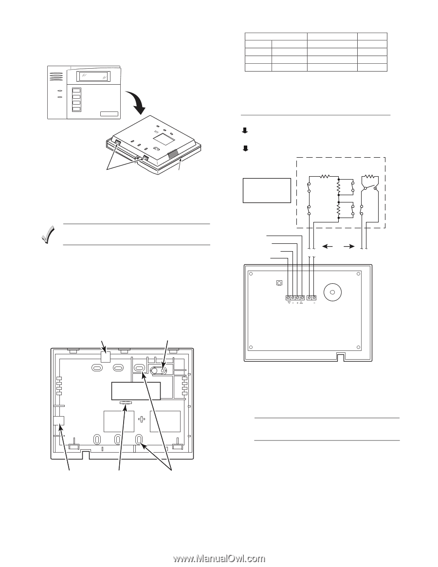
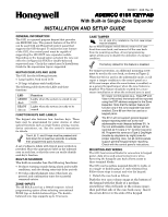
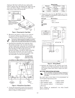
6150-006-V0 6151-003-V0 (between the front and back case) and gently twist to release the side locking tab. Repeat for the other side. Refer to Figure 1 for location of the case back release snaps and locking tabs. ARMED READY NOTE: TO REMOVE CASE BACK PUSH IN THE TWO MOUNTING SNAPS LOCATED ALONG THE BOTTOM OF THE KEYPAD AND LIFT UP. RETAINING SNAPS LOCKING TAB Figure 1. Removing the Case Back 2. Mount the case back to a wall or to an electrical box using the 25mm-long self-tapping screws supplied (anchors for drywall are not supplied). If you wish to tamper-protect the keypad for removal from the wall, use an additional mounting screw in the tamper hole in the case back (see Figure 2 for location). 3. Pass the four power/data wires and zone wires through the opening in the case back. If surface wiring is being used, wiring may be routed through the top or the bottom left-side breakout in the case back. See Figure 2. The breakouts must be punched out using a screwdriver before mounting the case back. If desired, wires may be strainrelieved to the wire tie point on the inside of the case back with a tie wrap (not supplied). BREAKOUT FOR SURFACE WIRING USE AN ADDITIONAL MOUNTING SCREW HERE IF BACK CASE TAMPER WILL BE USED Wiring Table Keypad Control Panel GM Data Out Data In − GND − Aux Pwr + +12VDC + Aux Pwr LY Data In Data Out Color Green Black Red Yellow 5. Connect the wires for the 2K EOLR zone to the screw terminals on keypad PC board as shown in Figure 3 and as follows: Keypad Wired Zone ZN1 LEGEND = - + Zone 1 - Zone 1 return NOTE THE CONTROL PANEL MUST SUPPORT DOUBLE BALANCED RESISTORS DOUBLE BALANCED 2K CONVENTIONAL EOLR 2K TAMPER CONTACTS 2K N.O. TAMPER CONTACTS 2K N.C. [Y] DATA IN [+] +12VDC IN [-] GROUND (-12V) [G] DATA OUT OR G Y ZN BREAKOUT FOR SURFACE WIRING WIRE TIE POINT MOUNTING HOLES 6151-001-V0 Figure 2. Wiring Entry (Case Back) 4. Connect the power/data wires to the four screw terminals on the keypad's PC board marked as shown in Figure 3 and as follows: Figure 3. Wiring Details 6. Reattach the keypad to the mounted case back. Attach the top of the keypad first, and then press the bottom section down until it snaps into place securely. SETTING THE KEYPAD OPTIONS UL For UL (and ETL) commercial burglary installations, the zone must be programmed as a 24-hour audible zone type. The 6151 allows seven items to be programmed via local keypad programming mode: • Keypad address • Tamper enable • Zone expander enable • Display option • Zone expander address • Sound option • Zone type These settings are maintained even when keypad power is removed. WWW.DIYWALWARMWFO.RUDM.ICOYM ALA-R2 -MFORUM.COM
-
 1
1 -
 2
2 -
 3
3 -
 4
4
 |
 |