Honeywell C7189U Owner's Manual - Page 3
Wiring, Operation - sensor
 |
View all Honeywell C7189U manuals
Add to My Manuals
Save this manual to your list of manuals |
Page 3 highlights
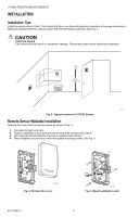
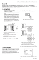
C7189U REMOTE INDOOR SENSOR WIRING The sensor can be used to provide one remote sensor (see Fig. 6) or as a temperature averaging network with multiple sensors connected (see Fig. 7). The thermostat is not part of the average network. CAUTION ELECTRICAL HAZARD. Can cause electrical shock or equipment damage. Disconnect power before wiring. 1. Run the wire cable from the thermostat to the remote sensor location. 2. Loosen screw terminals, insert wires into terminal block (polarity does not matter), then retighten screws. 3. Push excess wire back into the wall opening. 4. Plug the wall opening with non-flammable insulation to prevent drafts from affecting the sensor operation and replace the cover on the remote sensor. 5. Connect the two wires to the thermostat's remote sensor terminals (polarity does not matter) and replace the thermostat back onto the wallplate. See Fig. 6. M24116 Fig. 5. Terminal block wiring. C7189 3 2 Y2 Y2 RC R 1 W R W2 Y C S1 G S2 C 1 POWER SUPPLY. PROVIDE DISCONNECT MEANS AND OVERLOAD PROTECTION AS REQUIRED. 2 IF MORE THAN ONE C7189 REMOTE SENSOR IS REQUIRED, REFER TO FIGURE 7. 3 WIRES MUST HAVE A CABLE SEPARATE FROM THE THERMOSTAT CABLE. M19972A Fig. 6. Wiring a single C7189U Sensor. W2 1 1 2 S2 C7189 C7189 C7189 C7189 Y2 W2 1 1 2 2 C7189 C7189 C7189 C7189 C7189 C7189 C7189 C7189 C7189 OPERATION Once a remote indoor temperature sensor is connected to the thermostat, the thermostat's sensor is no longer used. The thermostat's installer setup should be modified to tell the thermostat that remote indoor temperature sensor(s) have been used. The Inside temperature reading on the thermostat's display will be the remote sensor(s) temperature location(s). See Fig. 8. 1 SENSORS MUST BE ARRANGED IN THIS CONFIGURATION TO OPERATE CORRECTLY. 2 WIRES MUST HAVE A CABLE SEPARATE FROM THE THERMOSTAT CABLE. M19973 Fig. 7. Wiring Multiple C7189U Sensors. . TUE FAN CHANGE FILTER UV LAMP HUMIDIFIER PAD Inside Set To AUTO Heat On SYSTEM Following Schedule HEAT AM SCHED HOLD CLOCK SCREEN MORE M19974 Fig. 8. Inside Temperature Reading on TH8000 Series Thermostat. 3 69-1710EFS-1
-
 1
1 -
 2
2 -
 3
3 -
 4
4 -
 5
5 -
 6
6 -
 7
7 -
 8
8 -
 9
9 -
10
-
11
-
12
 |
 |
