Honeywell CT1500 Owner's Manual - Page 13
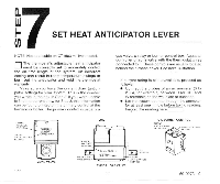
Set Heat Anticipator Lever
 |
View all Honeywell CT1500 manuals
Add to My Manuals
Save this manual to your list of manuals |
Page 13 highlights
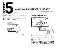
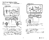
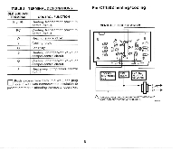
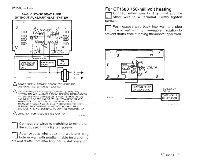
SET HEAT ANTICIPATOR LEVER - NOTE: Not applicable on CT1503 millivolt model. 0The thermostat's adjustable heat anticipator must be correctly set to accurately control the on-time length of the system. An incorrect setting can result in room temperature swings or burn out the anticipator and void the thermostat warranty. Make sure you have the current draw (anticipator setting) for your system. This i s the number you wrote in the box in Step 3 If you were unable to find the current draw for Step 3, this information can be found printed on the primary control at the furnace or boiler. The primary control is usually a gas valve a relay or burner controi box, Aquastat controller or zone valve with the thermostat wires connected to it These controls are usually located behind the furnace cover See next illustration If current rating is still unavailable, proceed as follows: Coqnect the probes of an ac ammeter (0 to 2.0 A,for example) between R (or RH) and W terminals on the wallplate or subbase. Let the system operate through the ammeter for at least one minute before taklng reading. Record the reading here
-
 1
1 -
2
-
3
-
4
-
5
-
6
-
7
-
 8
8 -
 9
9 -
 10
10 -
 11
11 -
 12
12 -
 13
13 -
 14
14 -
 15
15 -
 16
16 -
 17
17 -
 18
18 -
19
-
20
 |
 |
