Honeywell CT87B Owner's Manual - Page 9
IMPORTANT, CT87A, B, J ROUNDfi THERMOSTAT, This prevents the thermostat from being damaged. - thermostat installation
 |
UPC - 085267870245
View all Honeywell CT87B manuals
Add to My Manuals
Save this manual to your list of manuals |
Page 9 highlights
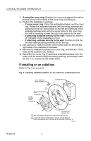
CT87A,B,J ROUND® THERMOSTAT 7 Mount the thermostat 1. Pull off the thermostat cover and discard the red plastic insert that holds the mercury switch in place during shipping. 2. Using a pencil point, slide the heat anticipator indicator to 1.2 on the scale as shown in Fig. 14. IMPORTANT: This prevents the thermostat from being damaged. Fig. 14. Adjusting heat anticipator indicator. HEAT ANTICIPATOR INDICATOR 1.2 .6 .5 .4 .3 .2 HOLE SUITABLE FOR PENCIL POINT TO MOVE INDICATOR .15 SCALE .12 .10 M20226 3. Place the thermostat over the wallplate or subbase so that the three captive mounting screws align with the three raised screw holes on the wallplate/subbase. 4. Tighten the three captive mounting screws as shown in Fig. 15. NOTE: These screws complete the installation of the thermostat. Fig. 15. Tightening mounting screws. CAPTIVE SCREWS (3) M20227 9 69-0274-6
-
 1
1 -
2
-
3
-
 4
4 -
 5
5 -
 6
6 -
 7
7 -
 8
8 -
 9
9 -
 10
10 -
 11
11 -
 12
12
 |
 |
