Honeywell HE220 Owner's Manual - Page 5
Installing the Sail Switch, Adapting Switch to Air Flow Direction - installation
 |
View all Honeywell HE220 manuals
Add to My Manuals
Save this manual to your list of manuals |
Page 5 highlights
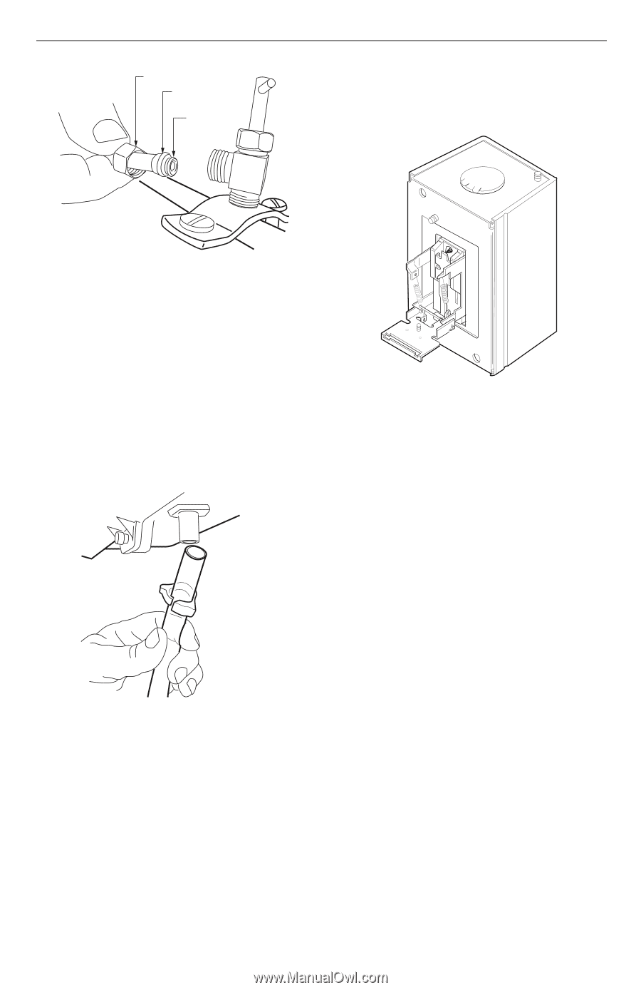
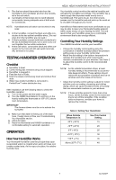
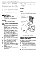
BRASS COMPRESSION NUT PLASTIC COMPRESSION RING BRASS INSERT HE220, HE260 HUMIDIFIER AND INSTALLATION KIT IMPORTANT Do not use the sail switch with both springs attached. Be sure to select air flow direction and remove spring(s) not required for installation. M20176 Fig. 9. Installing feed tubing. 4. Connect a 1/2 in. (13 mm) drain tube to the humidifier drain fitting and run to the floor drain (see Fig. 10). a. Slide the drain clamp over the tubing. b. Push the tubing over the drain nipple on the humidifier. c. Hand-tighten the clamp around the tubing to secure the humidifier drain. d. Fasten the drain tubing (can use duct tape) along the route to prevent movement and ensure downward slope for correct drainage. NOTE: Cut tubing to correct length so the tubing terminates at the drain. UP M3014 Fig. 11. Adapting sail switch to air flow direction or mounting position. • Vertical downward air flow: Leave the spring in place that is attached to the bracket marked Down. Remove the spring that is attached to the bracket marked Up. • Vertical upward air flow: Leave the spring in place that is attached to the bracket marked Up. Remove the spring that is attached to the bracket marked Down. • Horizontal air flow: Remove both springs. M20177 Fig. 10. Installing the drain tubing. Installing the Sail Switch Adapting Switch to Air Flow Direction The S688A Sail Switch has two counterbalancing springs in place as shown in Fig 11. These springs offset the effect of gravity for air flow direction. 1. Mount the template (provided with the sail switch) at the desired location. NOTE: Be sure the arrow (indicating air flow) points in the correct direction. a. For horizontal mounting, level the long dimension shown on the template. b. For vertical mounting, plumb the long dimension. 2. Cut the hole (indicated on the template) in the ductwork. 3. Center punch the screw holes indicated and drill out with a 1/8 in. (13 mm) drill. 4. Attach the sail to the switch as shown in Fig 12. 5 69-1645EF
-
 1
1 -
 2
2 -
 3
3 -
 4
4 -
 5
5 -
 6
6 -
 7
7 -
 8
8 -
 9
9 -
 10
10 -
 11
11 -
12
-
13
-
14
-
15
-
16
-
17
-
18
-
19
-
20
-
21
-
22
-
23
-
24
 |
 |