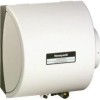
Honeywell HE260A1010 Installation Guide - Page 4
connecting PLUMBING - filter
 |
UPC - 085267207744
View all Honeywell HE260A1010 manuals
Add to My Manuals
Save this manual to your list of manuals |
Page 4 highlights
HE220, HE260 HUMIDIFIER INSTALLATION KIT SUMMER WINTER M20173 Fig. 6. Installing the starter collar. 12. Remove liner to expose foam adhesive. Position starter collar over opening. 13. Using sheet metal screws, connect starter collar to the duct and bypass duct from humidifier to starter collar. Be sure to secure the collar to the duct with sheet metal screws. See Fig. 7. CONNECTING PLUMBING Use hot or cold water and either hard or softened water in the humidifier. 1. Shut off the water. CAUTION Chemical Hazard. Can cause personal injury or equipment damage. Do not use any line connected to an air conditioner. Do not use gas line. 2. Use the self-piercing saddle valve (included) to tap into the water supply line at the location selected. See Fig. 8. If tapping into galvanized pipe, drain line and pre-drill 3/16 in. tap for saddle valve. NOTE: The saddle valve is not designed to regulate water flow. The valve is either open or closed. IMPORTANT To prevent debris from clogging the solenoid inline filter, be sure to install the saddle valve handle pointing toward the ceiling. SCREW DRIVER WATER LINE M20175 M20174 Fig. 7. Connecting bypass ducting. IMPORTANT To avoid sagging and stress on humidifier, add support if ducting is longer than 4 ft (1.25m). 14. Seal the duct connections with duct tape. 15. Reinstall the humidifier pad assembly in the humid- ifier housing. IMPORTANT Be sure to reconnect the water feed tube and ensure that the tube is not pinched or kinked. 16. Hinge the cover in place and secure with the thumbscrew located at the bottom of the cover. Fig. 8. Installing saddle valve. 3. Use 1/4 in. (6 mm) OD tubing and connect saddle valve to inlet side of the solenoid valve (see Fig. 9). a. Place brass compression nut over tubing. b. Install brass insert into end of tubing. c. Slide the plastic compression ring over the tubing. (Discard copper compression ring provided with valve.) NOTE: To prevent leaking, use plastic (Delrin) sleeve rings with plastic tubing. Use copper sleeve rings only with copper tubing. d. Insert the tubing into the solenoid valve fitting and support the valve while tightening the compression nut. NOTE: Do not over-tighten the compression nut. Moderate tightness prevents leaking. e. Repeat steps a. through d. for saddle valve fitting. f. Secure tubing with clamps provided. 69-1570 4


