Honeywell HE360A1043 Owner's Manual - Page 4
Installing the Sail Switch, Adapting Switch to Air Flow Direction
 |
View all Honeywell HE360A1043 manuals
Add to My Manuals
Save this manual to your list of manuals |
Page 4 highlights
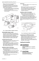
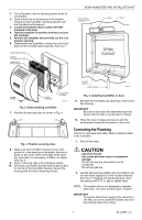
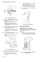
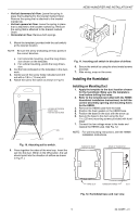
HE360 HUMIDIFIER AND INSTALLATION KIT SCREW DRIVER WATER LINE c. Hand-tighten the clamp around the tubing to secure the humidifier drain. d. Fasten the drain tubing (can use duct tape) along the route to prevent movement and ensure downward slope for correct drainage. NOTE: Cut tubing to correct length so the tubing terminates at the drain. M20175 Fig. 6. Installing the saddle valve. 3. Use 1/4 in. (6 mm) OD tubing and connect the saddle valve to the inlet side of the solenoid valveon the humidifier (see Fig. 7). a. Place the brass compression nut over the tubing. b. Install brass insert into end of tubing. c. Slide the plastic compression ring over the tubing. (Discard copper compression ring provided with valve.) NOTE: To prevent leaking, use plastic (Delrin) sleeve rings with plastic tubing. Use copper sleeve rings only with copper tubing. d. Insert the tubing into the solenoid valve fitting and support the valve while tightening the compression nut. NOTE: Do not over-tighten the compression nut. Moderate tightness prevents leaking. e. Repeat steps a. through d. for solenoid valve fitting. f. Secure tubing with clamps provided. M20177 Fig. 8. Installing the drain tubing. Installing the Sail Switch Adapting Switch to Air Flow Direction The S688A Sail Switch has two counterbalancing springs in place as shown in Fig 9. These springs offset the effect of gravity for air flow direction. IMPORTANT: Do not use the sail switch with both springs attached. Be sure to select air flow direction and remove spring(s) not required for installation. BRASS COMPRESSION NUT PLASTIC COMPRESSION RING BRASS INSERT UP M20176 Fig. 7. Installing feed tubing. 4. Connect a 1/2 in. (13 mm) drain tube to the humidifier drain fitting and run to the floor drain (see Fig. 8). a. Slide the drain clamp over the tubing. b. Push the tubing over the drain nipple on the humidifier. M3014 Fig. 9. Adapting sail switch to air flow direction or mounting position. 69-1646EF-01 4
-
 1
1 -
 2
2 -
 3
3 -
 4
4 -
 5
5 -
 6
6 -
 7
7 -
 8
8 -
 9
9 -
 10
10 -
11
-
12
-
13
-
14
-
15
-
16
-
17
-
18
-
19
-
20
-
21
-
22
-
23
-
24
 |
 |
