Honeywell HE360A1043 Owner's Manual - Page 5
Installing the Humidistat, Installing on Mounting Duct
 |
View all Honeywell HE360A1043 manuals
Add to My Manuals
Save this manual to your list of manuals |
Page 5 highlights
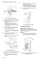
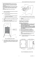
• Vertical downward air flow: Leave the spring in place that is attached to the bracket marked Down. Remove the spring that is attached to the bracket marked Up. • Vertical upward air flow: Leave the spring in place that is attached to the bracket marked Up. Remove the spring that is attached to the bracket marked Down. • Horizontal air flow: Remove both springs. HE360 HUMIDIFIER AND INSTALLATION KIT AIRFLOW 1. Mount the template (provided with the sail switch) at the desired location. NOTE: Be sure the arrow (indicating air flow) points in the correct direction. a. For horizontal mounting, level the long dimension shown on the template. b. For vertical mounting, plumb the long dimension. 2. Cut the hole (indicated on the template) in the ductwork. 3. Center punch the screw holes indicated and drill out with a 1/8 in. (13 mm) drill. 4. Attach the sail to the switch as shown in Fig 10. - LOOSEN SETSCREW - INSERT SAIL - TIGHTEN SETSCREW SAIL M20181 M20178 Fig. 11. Inserting sail switch in direction of airflow. 6. Secure the switch by using the sheet metal screws provided. 7. After wiring, snap on the cover. Installing the Humidistat Installing on Mounting Duct 1. Apply the template to the duct location chosen for the humidistat. Make sure the template is level before drilling the holes. 2. Refer to the template (provided with the H8908 Humidistat Installation Instructions) to drill the control assembly opening and mounting holes for the H8908. 3. Remove the H8908 case from the base. 4. Position the foam gasket on the H8908 base. 5. Position the base on the duct with the arrow up. 6. Secure the base to the duct using the four 1 in. (25 mm) mounting screws provided with humidistat. 7. Connect the low-voltage wires to the leads and replace the H8908 case. See Fig. 12. NOTE: For wall mounting instructions, see the H8908 Installation Instructions. Fig. 10. Attaching sail to switch. 5. Press together the sides of the wire loop. Insert the sail into the duct. (When in the Off position, the sail should point into the direction of airflow as shown in Fig.11.) HUMIDISTAT BASE REAR OF HUMIDISTAT WIRE SLOT HUMIDISTAT WIRES M20179 Fig. 12. Humidistat base and rear view. 5 69-1646EF-01
-
 1
1 -
 2
2 -
 3
3 -
 4
4 -
 5
5 -
 6
6 -
 7
7 -
 8
8 -
 9
9 -
 10
10 -
 11
11 -
12
-
13
-
14
-
15
-
16
-
17
-
18
-
19
-
20
-
21
-
22
-
23
-
24
 |
 |
