Honeywell HW1000i Owners Manual - Page 15
HW2000i Model, Engine Control Switch, Efficiency Mode Switch - manuals
 |
UPC - 894190002186
View all Honeywell HW1000i manuals
Add to My Manuals
Save this manual to your list of manuals |
Page 15 highlights
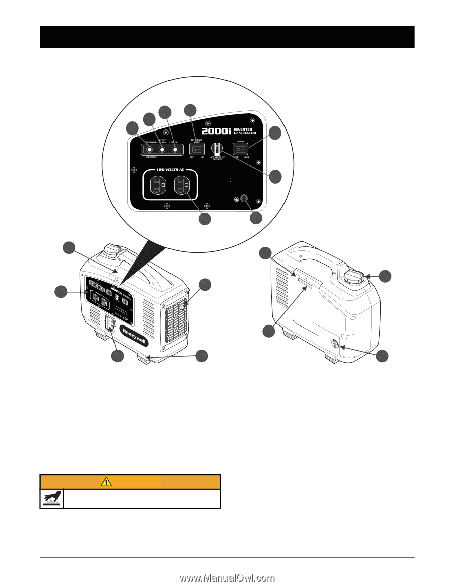
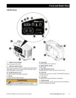
HW2000i Model Front and Back View Front and Back View 6 8 5 4 7 B A 2000 RATED WATTS 3 2100 MAXIMUM WATTS NEUTRAL FLOATING NEUTRE FLOTTANT 1 2 F G C I E D H 7. Engine Control Switch Turns the engine ON or OFF. 8. Efficiency Mode Switch When Efficiency Mode is ON, the engine speed will automatically adjust based on the connected load, resulting in better fuel consumption and less noise. B-Top Maintenance Cover Provides access to the engine spark plug. C-Muffler Provides outlet for engine exhaust. WARNING Muffler reaches temperatures that can cause serious burns if touched. NEVER touch hot surfaces. D-Case Feet Provides stability to the generator. E-Recoil Starter Handle Starts engine. F-Back Maintenance Cover Provides access to air filter, fuel filter, and oil fill cap. G-Fuel Cap Provides a secure seal on fuel tank. The HW1000i model has a vented fuel cap. H-Fuel Valve Controls flow of fuel from fuel tank to carburetor. I- Choke Control Controls choke valve. Choke control must be in the ON position when starting a cold engine. HW1000i / HW2000i Inverter Generator Owner's Manual www.honeywellgenerators.com 9
-
 1
1 -
2
-
3
-
4
-
5
-
6
-
7
-
8
-
9
-
 10
10 -
 11
11 -
 12
12 -
 13
13 -
 14
14 -
 15
15 -
 16
16 -
 17
17 -
 18
18 -
 19
19 -
 20
20 -
21
-
22
-
23
-
24
-
25
-
26
-
27
-
28
-
29
-
30
-
31
-
32
-
33
-
34
-
35
-
36
-
37
-
38
-
39
-
40
-
41
-
42
-
43
-
44
-
45
-
46
-
47
-
48
-
49
-
50
-
51
-
52
-
53
-
54
-
55
-
56
-
57
-
58
-
59
-
60
-
61
-
62
-
63
-
64
-
65
-
66
-
67
-
68
-
69
-
70
-
71
-
72
-
73
-
74
-
75
-
76
-
77
-
78
-
79
-
80
-
81
-
82
-
83
-
84
-
85
-
86
-
87
-
88
-
89
-
90
-
91
-
92
-
93
-
94
-
95
-
96
-
97
-
98
-
99
-
100
-
101
-
102
-
103
-
104
-
105
-
106
-
107
-
108
-
109
-
110
-
111
-
112
-
113
-
114
-
115
-
116
-
117
-
118
-
119
-
120
-
121
-
122
-
123
-
124
-
125
-
126
-
127
-
128
-
129
-
130
-
131
-
132
-
133
-
134
-
135
-
136
-
137
-
138
-
139
-
140
 |
 |