Honeywell MS9535-5 User Manual - Page 32
Cable Removal, Cradle Wall Mount, securing the cradle - metrologic
 |
View all Honeywell MS9535-5 manuals
Add to My Manuals
Save this manual to your list of manuals |
Page 32 highlights
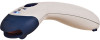
SCANNER OPERATION Cable Removal Before removing the cable from the scanner, Metrologic recommends that the power on the host device is off and the power supply has been disconnected from the PowerLink cable 1. Locate the small 'pinhole' on the bottom of the cradle near the cable. 2. Bend an ordinary paperclip into the shape shown above. 3. Insert the paperclip (or the small metallic pin) into the small 'pin-hole'. Figure 14. Cable Release 4. You will hear a faint 'click'. Pull gently on the strain-relief of the 10-pin, RJ45 cable to remove the cable from the cradle. Cradle Wall Mount z Metrologic provides two #7 wood screws for securing the cradle to the wall. z Figure 15 provides the pilot hole dimensions for securing the cradle base. z Install the cradle base to the wall. Figure 15. Hole Pattern Figure 16. Wall Attachment (left) and Wall Hook (right) 28
-
 1
1 -
2
-
3
-
4
-
5
-
6
-
7
-
8
-
9
-
10
-
11
-
12
-
13
-
14
-
15
-
16
-
17
-
18
-
19
-
20
-
21
-
22
-
23
-
24
-
25
-
26
-
 27
27 -
 28
28 -
 29
29 -
 30
30 -
 31
31 -
 32
32 -
 33
33 -
 34
34 -
 35
35 -
 36
36 -
 37
37 -
38
-
39
-
40
-
41
-
42
-
43
-
44
-
45
-
46
-
47
-
48
-
49
-
50
-
51
-
52
-
53
-
54
-
55
-
56
-
57
-
58
-
59
-
60
 |
 |
