Honeywell MS9535-5 User Manual - Page 8
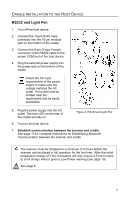
Scanner Components, Description - windows 7
 |
View all Honeywell MS9535-5 manuals
Add to My Manuals
Save this manual to your list of manuals |
Page 8 highlights
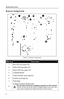
INTRODUCTION Scanner Components Figure 1. Scanner Components Item # Description 1 Blue LED (see pages 23) 2 White LED (see pages 23) 3 Amber LED (see pages 23) 4 CodeGate Button 5 Output Window, Laser Aperture 6 Speaker (see page 22) 7 Wrist Strap Charging Contacts /Rubber Feet 8 Do not short circuit the charging contacts on the scanner! A short circuit can occur when a metallic object such as a coin, clip or pen contacts the metal terminals of the scanner. 4
-
 1
1 -
2
-
 3
3 -
 4
4 -
 5
5 -
 6
6 -
 7
7 -
 8
8 -
 9
9 -
 10
10 -
 11
11 -
 12
12 -
 13
13 -
14
-
15
-
16
-
17
-
18
-
19
-
20
-
21
-
22
-
23
-
24
-
25
-
26
-
27
-
28
-
29
-
30
-
31
-
32
-
33
-
34
-
35
-
36
-
37
-
38
-
39
-
40
-
41
-
42
-
43
-
44
-
45
-
46
-
47
-
48
-
49
-
50
-
51
-
52
-
53
-
54
-
55
-
56
-
57
-
58
-
59
-
60
 |
 |

4
I
NTRODUCTION
Scanner Components
Figure 1. Scanner Components
Item #
Description
1
Blue LED
(see pages 23)
2
White LED
(see pages 23)
3
Amber LED
(see pages 23)
4
CodeGate Button
5
Output Window, Laser Aperture
6
Speaker
(see page 22)
7
Wrist Strap
8
Charging Contacts /Rubber Feet
Do not short circuit the charging contacts on the scanner!
A short circuit can occur when a metallic object such as a coin,
clip or pen contacts the metal terminals of the scanner.