Hotpoint HDA3500NBB Installation Instructions - Page 7
emo eon - manual
 |
View all Hotpoint HDA3500NBB manuals
Add to My Manuals
Save this manual to your list of manuals |
Page 7 highlights
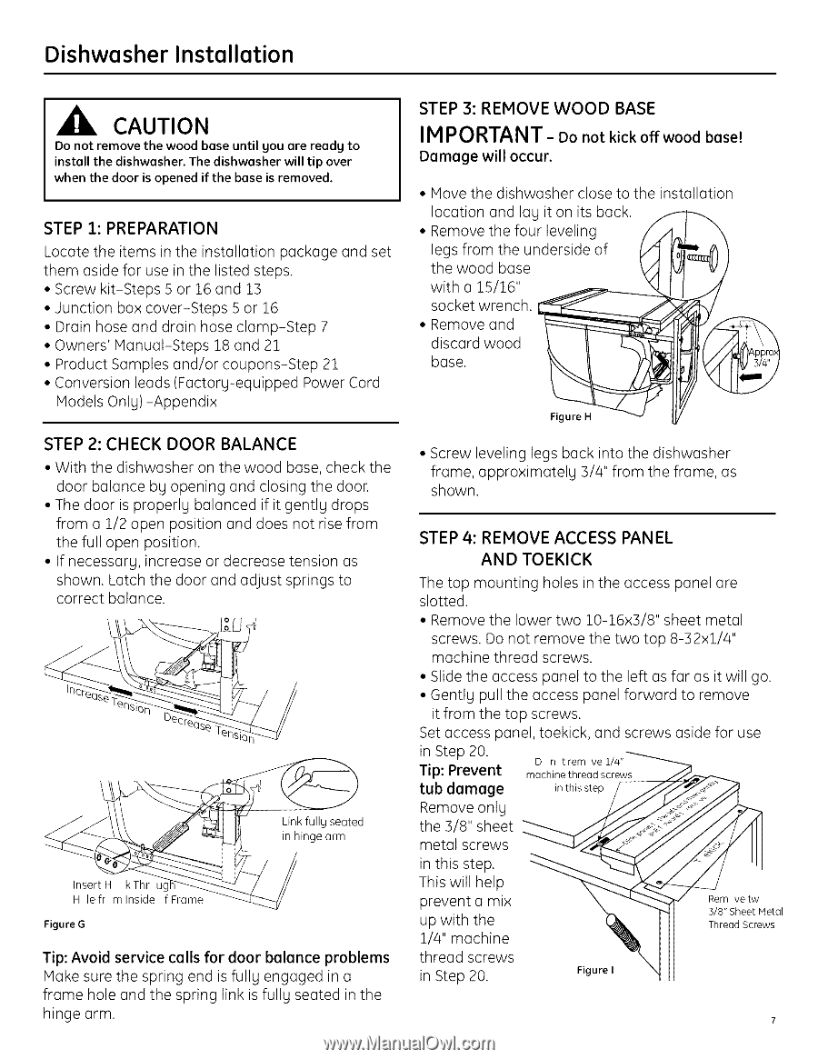
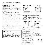
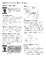
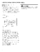
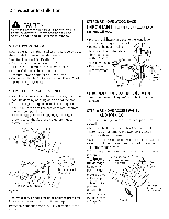
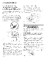
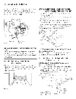
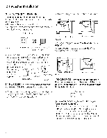
Dishwasher Installation CAUTION Do not remove the wood base until you are ready to install the dishwasher. The dishwasher will tip over when the door is opened if the base is removed. STEP 1: PREPARATION Locate the items in the installation package and set them aside for use in the listed steps. • Screw kit-Steps 5 or 16 and 13 • Junction box cover-Steps 5 or 16 • Drain hose and drain hose clamp-Step 7 • Owners' Manual-Steps 18 and 21 • Product Samples and/or coupons-Step 21 • Conversion leads (Factory-equipped Power Cord Models Only)-Appendix STEP 3: REMOVE WOOD BASE IM PORTANT - Donotkick off wood base! Damage will occur. • Move the dishwasher close to the installation location and lag it on its back. • Remove the four leveling legs from the underside of the wood base with a 15/16" socket wrench. discard wood base. STEP 2: CHECK DOOR BALANCE • With the dishwasher on the wood base, check the door balance bg opening and closing the door. • The door is properly balanced if it gently drops from a 1/2 open position and does not rise from the full open position. • If necessary, increase or decrease tension as shown. Latch the door and adjust springs to correct balance. Link fully seated in hinge arm Insert H kThr uc H lefr mlnside fFrame Figure G Tip: Avoid service calls for door balance problems Make sure the spring end is fully engaged in a frame hole and the spring link is full U seated in the hinge arm. • Screw leveling legs back into the dishwasher frame, approximately 3/4" from the frame, as shown. STEP 4: REMOVE ACCESS PANEL AND TOEKICK The top mounting holes in the access panel are slotted. • Remove the lower two 10-16x3/8" sheet metal screws. Do not remove the two top 8-32xl/4" machine thread screws. • Slide the access panel to the left as far as it will go. • Gently pull the access panel forward to remove it from the top screws. Set access panel, toekick, and screws aside for use in Step 20. D n trem ve 1/4"_ Tip: Prevent machine thread screws /J_- emo eon tub damage in this step _ _-_-_ the 3/8" sheet in this step. Tmheistawlsicllrehweslp "__ prevent a mix up with the 1/4" machine thread screws in Step 20. _ _ Figure _ _7"11 Remvetw 3/8" Sheet Metal Thread Screws
-
 1
1 -
 2
2 -
 3
3 -
 4
4 -
 5
5 -
 6
6 -
 7
7 -
 8
8 -
 9
9 -
 10
10 -
 11
11 -
 12
12 -
13
-
14
-
15
-
16
 |
 |