Hotpoint HDA3500NBB Installation Instructions - Page 8
Dishwasher, Installation, PORTANT
 |
View all Hotpoint HDA3500NBB manuals
Add to My Manuals
Save this manual to your list of manuals |
Page 8 highlights
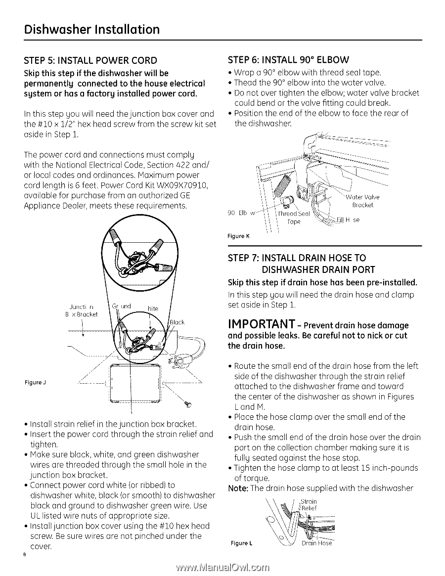
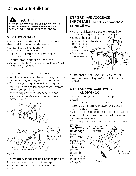
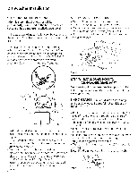
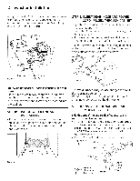
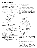
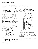
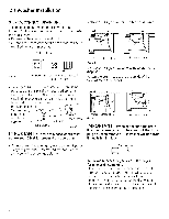
Dishwasher Installation STEP S: INSTALL POWER CORD Skip this step if the dishwasher will be permanently connected to the house electrical system or has a factory installed power cord. In this step you will need the junction box cover and the #10 x 1/2" hex head screw from the screw kit set aside in Step 1. STEP 6: INSTALL 90 ° ELBOW • Wrap a 90° elbow with thread seal tape. • Thead the 90 ° elbow into the water valve. • Do not over tighten the elbow; water valve bracket could bend or the valve fitting could break. • Position the end of the elbow to face the rear of the dishwasher. The power cord and connections must comply with the National Electrical Code, Section/422 and/ or local codes and ordinances. Maximum power cord length is 6 feet. Power Cord Kit WX09X70910 available for purchase from an authorized GE Appliance Dealer, meets these requirements. 90 EIb w / Tape Figure K _Water Valve Bracket m se Juncti n B x Bracket STEP 7: INSTALL DRAIN HOSE TO DISHWASHER DRAIN PORT Skip this step if drain hose has been pre-installed. In this step you will need the drain hose and clamp set aside in Step 1. Black IM PORTANT- Prevent drain hose damage and possible leaks. Be careful not to nick or cut the drain hose. \ Figure J • Install strain relief in the junction box bracket. • Insert the power cord through the strain relief and tighten. • Make sure black, white, and green dishwasher wires are threaded through the small hole in the junction box bracket. • Connect power cord white (or ribbed) to dishwasher white, black (or smooth) to dishwasher black and ground to dishwasher green wire. Use UL listed wire nuts of appropriate size. • Install junction box cover using the #10 hex head screw. Be sure wires are not pinched under the cover 8 • Route the small end of the drain hose from the left side of the dishwasher through the strain relief attached to the dishwasher frame and toward the center of the dishwasher as shown in Figures L and M. • Place the hose clamp over the small end of the drain hose. • Push the small end of the drain hose over the drain port on the collection chamber making sure it is fully seated against the hose stop. • Tighten the hose clamp to at least 15 inch-pounds of torque. Note: The drain hose supplied with the dishwasher ///Relief --_ / ,Strain Figure L
-
 1
1 -
2
-
 3
3 -
 4
4 -
 5
5 -
 6
6 -
 7
7 -
 8
8 -
 9
9 -
 10
10 -
 11
11 -
 12
12 -
 13
13 -
14
-
15
-
16
 |
 |