Hunter 21315 Owner's Manual - Page 15
Uninstalling the Light Fixture - parts
 |
View all Hunter 21315 manuals
Add to My Manuals
Save this manual to your list of manuals |
Page 15 highlights
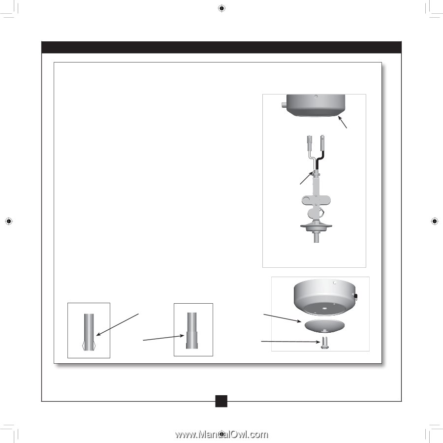
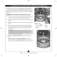
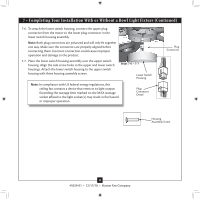
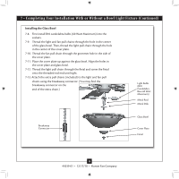
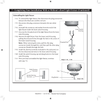
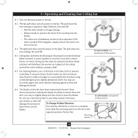
7 • Completing Your Installation With or Without a Bowl Light Fixture (Continued) Uninstalling the Light Fixture 7-14. To uninstall the light fixture, first disconnect the plug connectors between the black wire and the red wire. 7-15. Disconnect the plug connectors between the two white wires. 7-16. Uninstall the connector and washer from the end of the light fixture inside the lower switch housing. 7-17. Unscrew the threaded rod of the light fixture from the lower switch housing. 7-18. Remove the light fixture from the lower switch housing pulling disconnected wires through the hole in the center of the lower switch housing. Note: When removing the wires, pull the thin plug Threaded Rod connector (male) through first, and then pull the other plug connector (female) through the hole. 7-19. Install the dummy terminals (included in the sack parts) on the two disconnected wires in the lower switch housing. 7-20. Install the switch housing cap and plug button to the lower switch housing. 7-21. Once you have uninstalled the light fixture, continue with step 7‑6. Steps 7-16 - 7-18 Lower Switch Housing Male Dummy Terminal Female Dummy Terminal Cap Plug Button Step 7-20 15 45039-01 • 12/17/10 • Hunter Fan Company
-
 1
1 -
2
-
3
-
4
-
5
-
6
-
7
-
8
-
9
-
 10
10 -
 11
11 -
 12
12 -
 13
13 -
 14
14 -
 15
15 -
 16
16 -
 17
17
 |
 |