Hunter 21315 Owner's Manual - Page 7
For Angled Ceilings
 |
View all Hunter 21315 manuals
Add to My Manuals
Save this manual to your list of manuals |
Page 7 highlights
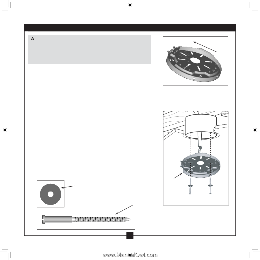
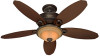
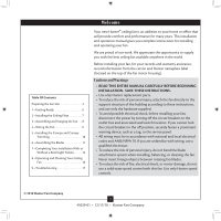
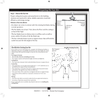
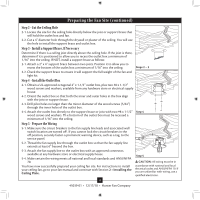
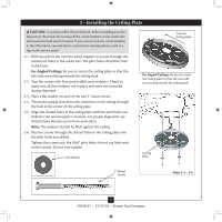
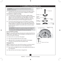
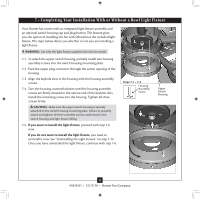
2 • Installing the Ceiling Plate CAUTION: To avoid possible electrical shock, before installing your fan, disconnect the power by turning off the circuit breakers to the outlet box and associated wall switch location. If you cannot lock the circuit breakers in the off position, securely fasten a prominent warning device, such as a tag, to the service panel. 2-1. Drill two pilot holes into the wood support structure through the outermost holes in the outlet box. The pilot holes should be 9/64" in diameter. For Angled Ceilings: Be sure to orient the ceiling plate so that the two tabs are pointing toward the ceiling peak. 2-2. Your fan comes with four preinstalled noise isolators. Check to make sure all four isolators are in place and were not removed during shipment. 2-3. Place a flat washer on each of the two 3" wood screws. 2-4. Thread the supply wires from the outlet box in the ceiling through the hole in the center of the ceiling plate. 2-5. Align the slotted holes in the ceiling plate with the pilot holes you drilled in the wood support structure. For proper alignment use slotted holes directly across from each other. Note: The isolators should be flush against the ceiling. 2-6. Pass the screws through the slotted holes in the ceiling plate into the pilot holes you drilled. Tighten the screws into the 9/64" pilot holes; do not use lubricants on the screws. Do not over tighten. Flat Washer Toward Ceiling Peak For Angled Ceilings: Be sure to orient the ceiling plate so that the two tabs are pointing toward the ceiling peak. Ceiling Plate 3" Wood Screw Steps 2-3 - 2-6 7 45039-01 • 12/17/10 • Hunter Fan Company
-
 1
1 -
 2
2 -
 3
3 -
 4
4 -
 5
5 -
 6
6 -
 7
7 -
 8
8 -
 9
9 -
 10
10 -
 11
11 -
 12
12 -
13
-
14
-
15
-
16
-
17
 |
 |