Hunter 82020 Owner's Manual - Page 6
Fan Motor, Light, Green, Black, White, Bare Copper, Ground, Main Switch 1 AC In, Switch 2 AC In,
 |
View all Hunter 82020 manuals
Add to My Manuals
Save this manual to your list of manuals |
Page 6 highlights
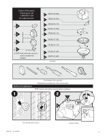
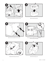
A3 Route wires through the strain relief. A4 Fan Motor Light 2 Pin Black White White 3 Pin Black Light *Option *Option Fan & Main Light Together Ground Green A Bare Copper Black Main Switch 1 (AC In) White Black Switch 2 (AC In) Connect wires as shown. A5 A06 E G F Install the wiring cover plate. Make sure all wiring connections are inside the box or under the wiring cover plate. 6 Connect 4" duct and vent to the outside. Tape joints. If ducting does not fit securely, an adapter may need to be purchased. 42947-01 01/12/2007
-
 1
1 -
 2
2 -
 3
3 -
 4
4 -
 5
5 -
 6
6 -
 7
7 -
 8
8 -
 9
9 -
 10
10 -
 11
11 -
 12
12 -
13
-
14
-
15
-
16
-
17
-
18
-
19
-
20
-
21
-
22
-
23
-
24
-
25
-
26
-
27
-
28
-
29
-
30
-
31
-
32
-
33
-
34
-
35
-
36
-
37
-
38
-
39
-
40
-
41
-
42
 |
 |

A
3 Pin
2 Pin
Fan Motor
Light
Light
Green
Black
Black
White
Black
Black
White
White
Bare Copper
Ground
A4
Main Switch 1 (AC In)
Switch 2 (AC In)
*Option Fan & Main Light Together
*Option
A3
Route wires through the strain relief.
Connect wires as shown.
0
0
A6
Connect 4” duct and vent to the outside. Tape joints.
If ducting does not fit securely, an adapter may need
to be purchased.
6
A5
E
F
G
Install the wiring cover plate. Make sure all
wiring connections are inside the box or under
the wiring cover plate.
42947-01
01/12/2007