Husqvarna LGT48DXL Owner Manual - Page 22
To Check Brake, Front Wheel Toe-in/camber, To Replace Mower Blade Drive Belt
 |
View all Husqvarna LGT48DXL manuals
Add to My Manuals
Save this manual to your list of manuals |
Page 22 highlights
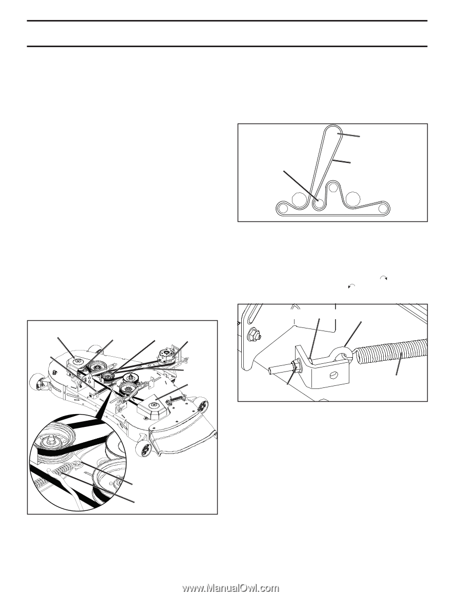
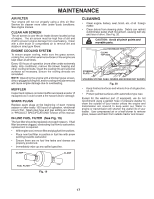
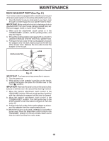
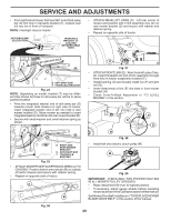
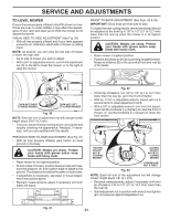
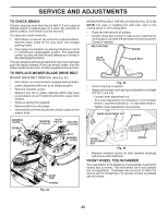
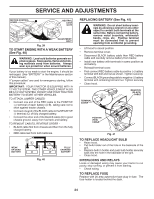
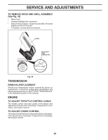
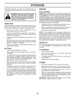
SERVICE AND ADJUSTMENTS TO CHECK BRAKE If tractor requires more than five (5) feet (1.5 m) to stop at highest speed in highest gear on a level, dry concrete or paved surface, then brake must be serviced. You may also check brake by: 1. Park tractor on a level, dry concrete or paved surface, depress brake pedal all the way down and engage parking brake. 2. Disengage transmission by placing freewheel control in "transmission disengaged" position. Pull freewheel control out and into the slot and release so it is held in the disengaged position. The rear wheels must lock and skid when you try to manually push the tractor forward. If the rear wheels rotate, then the brake needs to be serviced. Contact a qualified service center. TO REPLACE MOWER BLADE DRIVE BELT MOWER DRIVE BELT REMOVAL (See Fig. 34) • Park tractor on a level surface. Engage parking brake. • Lower attachment lift lever to its lowest position. • Remove mandrel covers. • Remove any dirt or grass clippings which may have accumulated around mandrels and entire upper deck surface. • Remove spring from eyebolt. • Remove belt from all pulleys. • Remove the belt from around the electric clutch on the engine shaft. MANDREL COVER EYEBOLT IDLER MANDREL PULLEY PULLEY ELECTRIC CLUTCH BELT MANDREL COVER IDLER ARM SPRING Fig. 34 MOWER DRIVE BELT INSTALLATION (See Fig. 35 & 36) NOTE: For ease in installing the deck belt, refer to the routing decal on the cutting deck. • Place the belt around all pulleys. • Double check belt routing to make sure it matches the routing decal, and that the belt does not have any twist. Correct if needed. BELT ROUTING ENGINE IDLER PULLEY BLADE BELT Fig. 35 • Connect spring to eyebolt. • Adjust belt tension until spring is extended to a length of 5.75" (14,6 cm). - Loosen inner adjustment nut. - Turn outer adjustment nut clockwise ( ) to increase tension, counterclockwise ( ) to decrease tension. - Tighten inner adjustment nut securely. INNER ADJUSTMENT NUT EYEBOLT OUTER ADJUSTMENT NUT SPRING Fig. 36 • Replace mandrel covers on both mandrel housings and secure with fasteners. FRONT WHEEL TOE-IN/CAMBER Your new tractor front wheel toe-in and camber is set at the factory and is normal. The front wheel toe-in and camber are not adjustable. If damage has occurred to affect the factory set front wheel toe-in or camber, contact a qualified service center. 22
-
 1
1 -
2
-
3
-
4
-
5
-
6
-
7
-
8
-
9
-
10
-
11
-
12
-
13
-
14
-
15
-
16
-
 17
17 -
 18
18 -
 19
19 -
 20
20 -
 21
21 -
 22
22 -
 23
23 -
 24
24 -
 25
25 -
 26
26 -
 27
27 -
28
-
29
-
30
-
31
-
32
-
33
-
34
-
35
-
36
-
37
-
38
-
39
-
40
-
41
-
42
-
43
-
44
-
45
-
46
-
47
-
48
-
49
-
50
-
51
-
52
-
53
-
54
-
55
-
56
-
57
-
58
-
59
-
60
 |
 |