Husqvarna LGT48DXL Owner Manual - Page 23
To Remove Wheel See Fig. 38, To Replace Motion Drive Belt, See Fig. 37, Transaxle, Motion Control
 |
View all Husqvarna LGT48DXL manuals
Add to My Manuals
Save this manual to your list of manuals |
Page 23 highlights
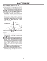
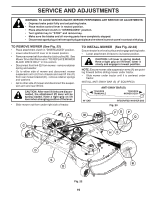
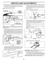
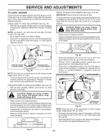
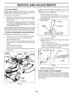
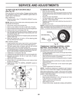
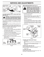
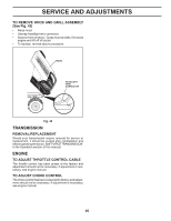
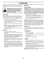
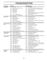
SERVICE AND ADJUSTMENTS TO REPLACE MOTION DRIVE BELT (See Fig. 37) Park the tractor on level surface. Engage parking brake. For assistance, there is a belt installation guide decal on bottom side of left footrest. BELT REMOVAL 1. Remove mower. (See "TO REMOVE MOWER" section in this manual.) NOTE: Observe entire motion drive belt and position of all belt guides and keepers. 2. Disconnect clutch wire harness (A). 3. Remove anti-rotation link (B) on right side of tractor. 4. Removebeltfromstationaryidler(C)andclutchingidler(D). 5. Remove belt from centerspan idler (E). 6. Pull belt slack toward rear of tractor. Carefully remove belt upwards from transmission input pulley and over cooling fan blades (F). 7. Remove belt downward from engine pulley and around electric clutch (G). 8. Slide belt toward rear of tractor, off the steering plate (H) and remove from tractor. BELT INSTALLATION 1. Install new belt from tractor rear to front, over the steer- ing plate (H) and above clutch brake pedal shaft (J). 2. Pull belt toward front of tractor and roll belt around electric clutch and onto engine pulley (G). 3. Pull belt toward rear of tractor. Carefully work belt down around transmission cooling fan and onto the input pulley (F). Be sure belt is inside the belt keeper. 4. Install belt on centerspan idler (E). 5. Installbeltthroughstationaryidler(C)andclutchingidler(D). 6. Reinstall anti-rotation link (B) on right side of tractor. Tighten securely. 7. Reconnect clutch harness (A). 8. Ensure belt is in all pulley grooves and inside all belt guides and keepers. 9. Install mower. (See "TO INSTALL MOWER" section in this manual.) B A C D E G H J F TO REMOVE WHEEL (See Fig. 38) • Block up axle securely. • Remove axle cover, retaining ring and washers to allow wheel removal (rear wheel contains a square key - Do not lose). • Repair tire and reassemble. • On rear wheels only: align grooves in rear wheel hub and axle. Insert square key. • Replace washers and snap retaining ring securely in axle groove. • Replace axle cover. NOTE: To seal tire punctures and prevent flat tires due to slow leaks, tire sealant may be purchased from your local parts dealer. Tire sealant also prevents tire dry rot and corrosion. WASHERS RETAINING RING AXLE COVER 00663 Fig. 38 TRANSAXLE MOTION CONTROL LEVER NEUTRAL ADJUSTMENT (See Fig. 39) The motion control lever has been preset at the factory and adjustment should not be necessary. • Loosen adjustment bolt in front of the right rear wheel, and lightly tighten. • Start engine and move motion control lever until tractor does not move forward or backward. • Hold motion control lever in that position and turn engine off. • While holding motion control lever in place, loosen the adjustment bolt. • Move motion control lever to the neutral (lock gate) position. • Tighten adjustment bolt securely. NOTE: If additional clearance is needed to get to adjustment bolt, move mower deck height to the lowest position. After above adjustment is made, if the tractor still creeps forward or backward while motion control lever is in neutral position, follow these steps: • Loosen the adjustment bolt. • Move motion control lever 1/4 to 1/2" (6.3 to 12.7 mm) in the direction it is trying to creep. • Tighten adjustment bolt securely. • Start engine and test. • If tractor still creeps, repeat above steps until satisfied. Fig. 37 23
-
 1
1 -
2
-
3
-
4
-
5
-
6
-
7
-
8
-
9
-
10
-
11
-
12
-
13
-
14
-
15
-
16
-
17
-
 18
18 -
 19
19 -
 20
20 -
 21
21 -
 22
22 -
 23
23 -
 24
24 -
 25
25 -
 26
26 -
 27
27 -
 28
28 -
29
-
30
-
31
-
32
-
33
-
34
-
35
-
36
-
37
-
38
-
39
-
40
-
41
-
42
-
43
-
44
-
45
-
46
-
47
-
48
-
49
-
50
-
51
-
52
-
53
-
54
-
55
-
56
-
57
-
58
-
59
-
60
 |
 |
