IBM 6656HG2 Service Manual - Page 9
Disassembly
 |
UPC - 087944642084
View all IBM 6656HG2 manuals
Add to My Manuals
Save this manual to your list of manuals |
Page 9 highlights
DISASSEMBLY 1. TILT SWIVEL REMOVAL (1) Remove the Cover Hinge. (2) Remove two screws (a). (3) Remove the Cover Piece Back. (4) Remove two connectors (c). Cover Piece Back (5) Remove the Module Link Cable connector. (6) Remove the screw (b). (7) Remove the Tilt Swivel. Cover Hinge Module Link Cabel (b) (c) (a) (a) 2. BACK COVER REMOVAL (1) Remove four Screw Covers (a). (2) Remove four screws (b). (3) Remove the Back Cover Ass'y. 3. CABINET ASS'Y REMOVAL (1) Remove four Screws (a). (2) Remove the Control PCB connerctor. (3) Remove the Cabinet Ass'y. (a) (b) Back Cover Cabinet (a) (b) (a) (b) (a) (b) (a) (a) Control PCB Connector (a) (a) -9-
-
 1
1 -
2
-
3
-
 4
4 -
 5
5 -
 6
6 -
 7
7 -
 8
8 -
 9
9 -
 10
10 -
 11
11 -
 12
12 -
 13
13 -
 14
14 -
15
-
16
-
17
-
18
-
19
-
20
-
21
-
22
-
23
-
24
-
25
-
26
-
27
-
28
-
29
-
30
-
31
-
32
-
33
-
34
 |
 |

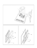
Back Cover
- 9 -
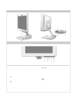
DISASSEMBLY
(a)
(b)
(a)
(c)
1. TILT SWIVEL REMOVAL
(1) Remove the Cover Hinge.
(2) Remove two screws (a).
(3) Remove the Cover Piece Back.
(4) Remove two connectors (c).
(5) Remove the Module Link Cable connector.
(6) Remove the screw (b).
(7) Remove the Tilt Swivel.
2. BACK COVER REMOVAL
(1) Remove four Screw Covers (a).
(2) Remove four screws (b).
(3) Remove the Back Cover Ass’y.
(b)
(b)
(a)
(a)
(a)
(a)
(b)
(b)
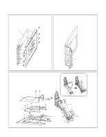
3. CABINET ASS’Y REMOVAL
(1) Remove four Screws (a).
(2) Remove the Control PCB connerctor.
(3) Remove the Cabinet Ass’y.
(a)
(a)
(a)
(a)
Cover Hinge
Cover Piece Back
Module Link Cabel
Cabinet
Control PCB Connector