IBM 6792 User Guide
IBM 6792 - NetVista M41 - 256 MB RAM Manual
 |
UPC - 087944764670
View all IBM 6792 manuals
Add to My Manuals
Save this manual to your list of manuals |
IBM 6792 manual content summary:
- IBM 6792 | User Guide - Page 1
User Guide Type 2292, 6343, 6349, 6350 Type 6790, 6791, 6792, 6793, 6794, 6795 Type 6823, 6825 - IBM 6792 | User Guide - Page 2
- IBM 6792 | User Guide - Page 3
User Guide Type 2292, 6343, 6349, 6350 Type 6790, 6791, 6792, 6793, 6794, 6795 Type 6823, 6825 - IBM 6792 | User Guide - Page 4
Note Before using this information and the product it supports, be sure to read the "Safety Information" on page v and "Appendix E. Notices and trademarks" on page 69. . US Government Users Restricted Rights - Use, duplication or disclosure restricted by GSA ADP Schedule Contract with IBM Corp. - IBM 6792 | User Guide - Page 5
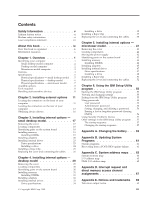
IBM Setup Utility program . . 57 The startup sequence 57 Changing the startup sequence 57 Appendix A. Changing the battery . . . 59 Appendix B. Updating System Programs 61 System programs 61 Recovering from a POST/BIOS update failure . . . 61 Appendix C. System address maps . . 63 System memory - IBM 6792 | User Guide - Page 6
Trademarks 70 Index 71 iv User Guide - IBM 6792 | User Guide - Page 7
telecommunications systems, networks, and modems before you open the device covers, unless instructed otherwise in the installation and configuration procedures. v Connect and disconnect cables as cordons d'alimentation, ainsi que les câbles qui la relient aux © Copyright IBM Corp. 2001 v - IBM 6792 | User Guide - Page 8
ou des périphériques qui lui sont raccordés, reportez-vous aux instructions ci-dessous pour connecter et déconnecter les différents cordons. Connexion is incorrectly replaced. When replacing the battery, use only IBM Part Number 33F8354 or an equivalent type battery recommended by . vi User Guide - IBM 6792 | User Guide - Page 9
à proximité de la fuite. Laser compliance statement Some IBM Personal Computer models are equipped from the factory with a is installed, note the following handling instructions. CAUTION: Use of controls or to hazardous laser radiation. There are no serviceable parts inside the CD-ROM drive or DVD - IBM 6792 | User Guide - Page 10
est ouvert. Évitez toute exposition directe des yeux au rayon laser. Évitez de regarder fixement le faisceau ou de l'observer à l'aide d'instruments optiques. viii User Guide - IBM 6792 | User Guide - Page 11
for removing the cover and installing hard disk drives, memory, and adapters in your computer. v "Chapter 6. Using the IBM Setup Utility program" provides instructions for updating the computer configuration, using passwords, and changing the startup sequence. v "Appendix A. Changing the - IBM 6792 | User Guide - Page 12
includes basic troubleshooting information, software recovery procedures, help and service information, and warranty information. Access IBM provides a link to more information about your computer. Click Start → Access IBM. If you have Internet access, the most up-to-date manuals for your computer - IBM 6792 | User Guide - Page 13
general information about the use, operation, and maintenance of your computer. Access IBM also contains information to help you solve problems and get repair service or other technical assistance. Identifying your computer To properly install options, you will need to know the machine type/model - IBM 6792 | User Guide - Page 14
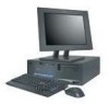
Small desktop model computer Desktop model computer Microtower model computer 2 User Guide - IBM 6792 | User Guide - Page 15
Features This section provides an overview of the computer features, preinstalled software, and specifications. Microprocessor Intel® Pentium™ 4 with 256 KB of internal L2 cache memory and Intel NetBurst™ micro-architecture Memory v Support for three dual in-line memory modules (DIMMs) (some models - IBM 6792 | User Guide - Page 16
control v Security profile by device IBM preinstalled software Your computer might come with preinstalled software. If it does, an operating system, device drivers to support built-in features, and other support programs are included. Operating systems (supported) v Microsoft® Windows XP v Microsoft - IBM 6792 | User Guide - Page 17
: Power consumption and heat output vary depending on the number and type of optional features installed and the power-management optional features in use. Chapter 1. Overview 5 - IBM 6792 | User Guide - Page 18
: Power consumption and heat output vary depending on the number and type of optional features installed and the power-management optional features in use. 6 User Guide - IBM 6792 | User Guide - Page 19
: Power consumption and heat output vary depending on the number and type of optional features installed and the power-management optional features in use. Chapter 1. Overview 7 - IBM 6792 | User Guide - Page 20
a SCSI adapter) v Internal options - System memory, called dual in-line memory modules (DIMMs) - Adapters - Peripheral component interconnect Wide Web pages: v http://www.ibm.com/pc/us/options/ v http://www.pc.ibm.com/support/ You can also obtain information by instructed to do so. 8 User Guide - IBM 6792 | User Guide - Page 21
cause static electricity to build up around you. v Always handle components carefully. Handle adapters and memory modules by the edges. Never touch any exposed circuitry. v Prevent others from touching components. v place the option on the computer cover or other metal surface. Chapter 1. Overview 9 - IBM 6792 | User Guide - Page 22
10 User Guide - IBM 6792 | User Guide - Page 23
the required connector, and then use the instructions that come with the option to help you make the connection and install any software or device drivers that are required for the option. Important Before the small desktop computer. 1 USB connector 2 USB connector © Copyright IBM Corp. 2001 11 - IBM 6792 | User Guide - Page 24
shows the location of the connectors on the front of the microtower computer. Note: Not all computer models will have the following connectors. 12 User Guide 1 IEEE 1394 connector 2 Microphone connector 3 Headphone connector 4 USB connector 5 USB connector - IBM 6792 | User Guide - Page 25
1 Mouse connector 2 Parallel connector 3 Audio line in connector 4 Power connector 5 PCI slots 6 AGP slot 7 Audio line out connector 8 Microphone connector 9 Ethernet connector 10 Serial connector 11 Serial connector 12 USB connectors 13 Keyboard connector Note: Some connectors on the rear of the - IBM 6792 | User Guide - Page 26
1 Power connector 2 Mouse connector 3 Parallel connector 4 Audio line in connector 5 PCI slots 6 AGP slot 7 Audio line out connector 8 Microphone connector 9 Ethernet connector 10 Serial connector 11 Serial connector 12 USB connectors 13 Keyboard connector Note: Some connectors on the rear of the - IBM 6792 | User Guide - Page 27
computer. See page 16 for connector descriptions. 1 Mouse connector 2 Keyboard connector 3 USB connectors 4 Serial connector 5 Parallel connector 6 Serial connector 7 Ethernet connector 8 Microphone connector 9 Audio line out connector 10 Audio line in connector 11 AGP slot 12 PCI slots 13 Power - IBM 6792 | User Guide - Page 28
. Ethernet connector Used to attach an Ethernet cable drivers You can obtain device drivers for operating systems that are not preinstalled at http://www.pc.ibm.com/support/ on the World Wide Web. Installation instructions are provided in README files with the device driver files. 16 User Guide - IBM 6792 | User Guide - Page 29
can expand the capabilities of your computer by adding memory, drives, or adapters. When installing an option, use these instructions along with the instructions that come with the option. Removing the cover end of the cover up toward the front of the computer. © Copyright IBM Corp. 2001 17 - IBM 6792 | User Guide - Page 30
DVD drive 8 Diskette drive Identifying parts on the system board The system board, also called the planar or motherboard, is the main circuit board in your computer. It provides basic computer functions and supports a variety of devices that are IBM-installed or that you can install later. 18 User - IBM 6792 | User Guide - Page 31
audio connector 14 AGP slot 15 12V Power connector Installing memory Your computer has three connectors for installing dual in-line memory modules (DIMMs) that provide up to a maximum of 1 GB of system memory. Note: Your computer will only support DIMM 1 and DIMM 2 (from left to right). DIMM 3 will - IBM 6792 | User Guide - Page 32
on page 26. Installing adapters This section provides information and instructions for installing and removing adapters. Your computer has three used for an AGP adapter. Adapters must be low profile. Your computer supports adapters up to 168 mm (6.6 inches) long. To install an adapter: 1. - IBM 6792 | User Guide - Page 33
the drive bay cage upward, as shown, until it is latched in the up position. Repeat this procedure for the remaining drive bay. 3. Remove the support bar by pulling it outward from the computer. Chapter 3. Installing internal options - small desktop model 21 - IBM 6792 | User Guide - Page 34
from its static-protective package. 6. Install the adapter into the appropriate slot on the system board. 7. Install the adapter slot cover latch. 8. Replace the support bar and pivot the two drive bays back to their original positions. What to do next: v To work with another option, go to the - IBM 6792 | User Guide - Page 35
drives This section provides information and instructions for installing and removing internal drives the internal drive cables to the installed drive. Drive specifications Your computer might come with the following IBM-installed drives: v A 3.5-inch diskette drive in bay 1 v A CD drive or DVD drive - IBM 6792 | User Guide - Page 36
it is latched in the up position. 6. Install the drive into the bay. Align the screw holes and insert the two screws. 24 User Guide 7. Each integrated drive electronics (IDE) drive requires two cables; a four-wire power cable that connects to the power supply, and a signal cable that connects - IBM 6792 | User Guide - Page 37
To connect a CD drive or DVD drive to your computer, follow these steps. a. Locate the signal cable that came with your computer or with the new drive. b. Locate the secondary IDE connector on the system board. See "Identifying parts on the system board" on page 18. c. Connect one end of the signal - IBM 6792 | User Guide - Page 38
cables, including telephone lines and power cords. Also, depending on the option that is installed, you might need to confirm the updated information in the IBM Setup Utility program. To replace the cover and connect cables to your computer: 1. Ensure that all components have been reassembled - IBM 6792 | User Guide - Page 39
into place. 4. Reconnect the external cables and power cords to the computer. See "Chapter 2. Installing external options" on page 11. 5. To update the configuration, see "Chapter 6. Using the IBM Setup Utility program" on page 55. Chapter 3. Installing internal options - small desktop model 27 - IBM 6792 | User Guide - Page 40
28 User Guide - IBM 6792 | User Guide - Page 41
can expand the capabilities of your computer by adding memory, drives, or adapters. When installing an option, use these instructions along with the instructions that come with the option. Removing the cover rear end of the cover up toward the front of the computer. © Copyright IBM Corp. 2001 29 - IBM 6792 | User Guide - Page 42
10 AGP slot 11 PCI slots Identifying parts on the system board The system board, also called the planar or motherboard, is the main circuit board in your computer. It provides basic computer functions and supports a variety of devices that are IBM-installed or that you can install later. 30 User - IBM 6792 | User Guide - Page 43
connector sequentially, starting at DIMM 1 v Use 3.3 V, synchronous, 168-pin, unbuffered, 133 MHz nonparity synchronous dynamic random access memory (SDRAM) v Use 64 MB, 128 MB, 256 MB, or 512 MB DIMMs in any combination v DIMM heights of 38.1 mm (1.5 inches) To install a DIMM: 1. Remove - IBM 6792 | User Guide - Page 44
complete the installation, go to "Replacing the cover and connecting the cables" on page 38. Installing adapters This section provides information and instructions for installing and removing adapters. Your computer has three expansion slots for PCI adapters and one slot used for an AGP adapter. You - IBM 6792 | User Guide - Page 45
section. v To complete the installation, go to "Replacing the cover and connecting the cables" on page 38. Installing internal drives This section provides information and instructions for installing and removing internal drives. Chapter 4. Installing internal options - desktop model 33 - IBM 6792 | User Guide - Page 46
to the installed drive. Drive specifications Your computer comes with the following IBM-installed drives: v A CD-ROM drive in bay 1 (some models The following illustration shows the locations of the drive bays. 34 User Guide The following table describes some of the drives that you can install - IBM 6792 | User Guide - Page 47
Notes: 1. Drives that are greater than 41.3 mm (1.6 in.) high cannot be installed. 2. Install removable media (tape or CD) drives in the accessible bay: bay 1 or 2. Installing a drive To install an internal drive, follow these steps. 1. Remove the cover. See "Removing the cover" on page 29. 2. If - IBM 6792 | User Guide - Page 48
) drive requires two cables; a four-wire power cable that connects to the power supply and a signal cable that connects to the system board. 36 User Guide The steps to connect an IDE drive are different depending on the type of drive you are connecting. Locate the procedure below for your drive - IBM 6792 | User Guide - Page 49
3. Connect one end of the signal cable to the drive and the other to the secondary IDE connector on the system board. To reduce electronic noise, use the connectors at the end of the cable only. 4. Your computer has extra power connectors for additional drives. Connect a power connector to the drive - IBM 6792 | User Guide - Page 50
, including telephone lines and power cords. Also, depending on the option that is installed, you might need to confirm the updated information in the IBM Setup Utility program. To replace the cover and connect cables to your computer: 1. Ensure that all components have been reassembled correctly - IBM 6792 | User Guide - Page 51
it snaps into place. 4. Reconnect the external cables and power cords to the computer. See "Chapter 2. Installing external options" on page 11. 5. To update the configuration, see "Chapter 6. Using the IBM Setup Utility program" on page 55. Chapter 4. Installing internal options - desktop model 39 - IBM 6792 | User Guide - Page 52
40 User Guide - IBM 6792 | User Guide - Page 53
expand the capabilities of your computer by adding memory, drives, or adapters. When installing an option, use these instructions along with the instructions that come with the option. Removing the cover release button on the left side cover and remove the cover. © Copyright IBM Corp. 2001 41 - IBM 6792 | User Guide - Page 54
reach. Use the following procedure to provide easier access to the system board. 1. Locate the power supply. See "Locating components" on page 42. 42 User Guide - IBM 6792 | User Guide - Page 55
on the system board The system board, also called the planar or motherboard, is the main circuit board in your computer. It provides basic computer functions and supports a variety of devices that are IBM-installed or that you can install later. Chapter 5. Installing internal options - microtower - IBM 6792 | User Guide - Page 56
sequentially, starting at DIMM 1 v Use 3.3 V, synchronous, 168-pin, unbuffered, 133 MHz nonparity synchronous dynamic random access memory (SDRAM) v Use 64 MB, 128 MB, 256 MB, or 512 MB DIMMs in any combination v DIMM heights to the DIMM slots. See "Installing adapters" on page 45. 44 User Guide - IBM 6792 | User Guide - Page 57
complete the installation, go to "Replacing the cover and connecting the cables" on page 52. Installing adapters This section provides information and instructions for installing and removing adapters. Your computer has three expansion slots for PCI adapters and one slot used for an AGP adapter. You - IBM 6792 | User Guide - Page 58
2. Remove the adapter slot cover latch and the slot cover for the appropriate expansion slot. 3. Remove the adapter from its static-protective package. 4. Install the adapter into the appropriate slot on the system board. 5. Install the adapter slot cover latch. 46 User Guide - IBM 6792 | User Guide - Page 59
52. Installing internal drives This section provides information and instructions for installing and removing internal drives. Internal drives cables to the installed drive. Drive specifications Your computer comes with the following IBM-installed drives: v A CD drive or DVD drive in bay 1 (some - IBM 6792 | User Guide - Page 60
the drive. 3. Remove the bay panel from the drive bay by inserting a flat-blade screwdriver at the end and gently prying it loose. 48 User Guide - IBM 6792 | User Guide - Page 61
4. Remove the metal shield from the drive bay by inserting a flat-blade screwdriver into one of the slots and gently prying it loose. 5. Make sure the drive that you are installing is set correctly as either a master or a slave device. v If it is the first CD drive or DVD drive, set as a master - IBM 6792 | User Guide - Page 62
the power supply and a signal cable that connects to the system board. For a CD-ROM drive, you might also have an audio cable. 50 User Guide The steps to connect an IDE drive are different depending on the type of drive you are connecting. Locate the procedure below for your drive - IBM 6792 | User Guide - Page 63
5. If you have a CD-ROM audio cable, connect it to the drive and to the system board. See "Identifying parts on the system board" on page 43. To connect an additional IDE CD drive or DVD drive 1. Locate the secondary IDE connector on the system board and the three-connector signal cable. See " - IBM 6792 | User Guide - Page 64
, including telephone lines and power cords. Also, depending on the option that is installed, you might need to confirm the updated information in the IBM Setup Utility program. To replace the cover and connect cables to your computer: 1. Ensure that all components have been reassembled correctly - IBM 6792 | User Guide - Page 65
rail guides on the bottom of the cover engage the rails and push the cover closed until it latches. 4. Reconnect the external cables and power cords to the computer. See "Chapter 2. Installing external options" on page 11. 5. To update the configuration, see "Chapter 6. Using the IBM Setup Utility - IBM 6792 | User Guide - Page 66
54 User Guide - IBM 6792 | User Guide - Page 67
Utility program is stored in the electrically erasable programmable read-only memory (EEPROM) of your computer. The IBM Setup Utility program is used to view and change the configuration settings of your computer, regardless of which operating system you are using. However, the - IBM 6792 | User Guide - Page 68
password. After you set an administrator password, a password prompt is displayed each time you try to access the IBM Setup Utility program. If you type the wrong password, you will see an error message. If you type the computer will power off. 9. Repeat steps 2 through 4 on page 56. 56 User Guide - IBM 6792 | User Guide - Page 69
Setup Utility program menu and select Exit and then Save Settings. Other settings in the IBM Setup Utility program The information in this section contains instructions for changing the startup sequence. The startup sequence Your computer can be started from several devices including the hard disk - IBM 6792 | User Guide - Page 70
Setup Utility program (see "Starting the IBM Setup Utility program" on page 55). 2. Select Startup. 3. Select , the Automatic Startup Sequence, and the Error Startup Sequence. 5. Select Exit from the IBM Setup Utility menu and then Save Settings. If you have changed these settings and want to - IBM 6792 | User Guide - Page 71
Your computer has a special type of memory that maintains the date, time, and settings 32 (desktop model), or "Installing adapters" on page 45 (microtower model) for instructions for replacing adapters. 8. Replace the cover, and plug in the power cord. model). © Copyright IBM Corp. 2001 59 - IBM 6792 | User Guide - Page 72
replacement, an error message might be displayed. This is normal after replacing the battery. 9. Turn on the computer and all attached devices. 10. Use the IBM Setup Utility program to set the date and time and any passwords. 60 User - IBM 6792 | User Guide - Page 73
referred to as flash memory). You can easily update POST, BIOS, and the IBM Setup Utility program by starting your computer using a flash update diskette. IBM might make changes and enhancements to the system programs. When updates are released, they are available as downloadable files on the World - IBM 6792 | User Guide - Page 74
8. Insert the POST/BIOS update (flash) diskette into drive A, and turn on the computer and the monitor. 9. After the update session is completed, (microtower model). 12. Remove any adapters that impede access to the BIOS Configuration jumper. 13. Replace the Clear CMOS/Recovery jumper to its original - IBM 6792 | User Guide - Page 75
00000000. A 256-byte area and a 1 KB area of this RAM are reserved for BIOS data. Memory can be mapped differently if POST detects an error. Table 1. System memory map Address range (decimal) Address range (hex) 0 K - Real-time clock, address Real-time clock, data © Copyright IBM Corp. 2001 63 - IBM 6792 | User Guide - Page 76
IDE channel 1 command LPT2 Available Video Video LPT1 Video Video Video Available Available COM3 or COM4 Diskette channel 1 Primary IDE channel command port 64 User Guide - IBM 6792 | User Guide - Page 77
0001 Channel 0, transfer count register 0002 Channel 1, memory address register 0003 Channel 1, transfer count register 0004 Channel 2, memory address register 0005 Channel 2, transfer count register 0006 Channel 3, memory address register 0007 Channel 3, transfer count register 0008 - IBM 6792 | User Guide - Page 78
00C4 Channel 5, memory address register 00C6 Channel 5, transfer count register 00C8 Channel 6, memory address register 00CA Channel 6, transfer count register 00CC Channel 7, memory address register 00CE 00 - 03 00 - 03 00 - 07 Byte pointer Yes Yes Yes Yes Yes Yes Yes Yes 66 User Guide - IBM 6792 | User Guide - Page 79
Appendix D. Interrupt request and direct memory access channel assignments The following tables list the IRQ and DMA channel assignments. Table 4. IRQ channel assignments IRQ NMI SMI 0 1 2 3 Parallel port (for ECP or EPP) Reserved (cascade channel) Open Open Open © Copyright IBM Corp. 2001 67 - IBM 6792 | User Guide - Page 80
68 User Guide - IBM 6792 | User Guide - Page 81
right may be used instead. However, it is the user's responsibility to evaluate and verify the operation of any non-IBM product, program, or service. IBM may have patents or pending patent applications covering subject matter described in this document. The furnishing of this document does not - IBM 6792 | User Guide - Page 82
prohibited. The following terms are trademarks of the IBM Corporation in the United States or other countries or both: IBM Wake on LAN PS/2 Pentium and NetBurst are States, other countries, or both. Other company, product, and service names may be trademarks or service marks of others. 70 User Guide - IBM 6792 | User Guide - Page 83
model 52 small desktop model 26 D device, drivers 16 DIMMs, installing 19, 31, 44 DMA channel Ethernet connector 13, 14, 15, 16 I IBM Setup Utility 55 input/output (I/O) address map 63, 65 DMA address map 65 features 3 installing options desktop model adapters 32 DIMMs 31 internal drives 35 memory - IBM 6792 | User Guide - Page 84
Power Interface (ACPI) support 4 Advanced Power Management support 4 R recovering from a POST/BIOS update failure 61 removing the 44 identifying parts 18, 30, 43 location 19, 31, 44 memory 8, 18, 31, 43 system programs, updating 61 U updating system programs 61 USB connectors 13, 14, 15, 16 using, - IBM 6792 | User Guide - Page 85
- IBM 6792 | User Guide - Page 86
Part Number: 25P4024 Printed in the United States of America on recycled paper containing 10% recovered post-consumer fiber. (1P) P/N: 25P4024
-
 1
1 -
 2
2 -
 3
3 -
 4
4 -
 5
5 -
 6
6 -
 7
7 -
8
-
9
-
10
-
11
-
12
-
13
-
14
-
15
-
16
-
17
-
18
-
19
-
20
-
21
-
22
-
23
-
24
-
25
-
26
-
27
-
28
-
29
-
30
-
31
-
32
-
33
-
34
-
35
-
36
-
37
-
38
-
39
-
40
-
41
-
42
-
43
-
44
-
45
-
46
-
47
-
48
-
49
-
50
-
51
-
52
-
53
-
54
-
55
-
56
-
57
-
58
-
59
-
60
-
61
-
62
-
63
-
64
-
65
-
66
-
67
-
68
-
69
-
70
-
71
-
72
-
73
-
74
-
75
-
76
-
77
-
78
-
79
-
80
-
81
-
82
-
83
-
84
-
85
-
86
 |
 |

User Guide
Type 2292, 6343, 6349, 6350
Type 6790, 6791, 6792, 6793, 6794, 6795
Type 6823, 6825
±²³