IBM 86595RY Hardware Maintenance Manual - Page 137
If you are installing or removing a drive in bays A, Set the cover aside in a safe place.
 |
UPC - 087944501831
View all IBM 86595RY manuals
Add to My Manuals
Save this manual to your list of manuals |
Page 137 highlights
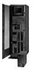
4. Pull the rack model out of the rack enclosure until both slide rails lock. Note When the server is in the locked position, you can easily reach the cables on the back of the server. 5. Remove the top cover. a. Locate the captive thumbscrew 1 on the back of the cover and turn it to release the cover. b. Slide the cover back about 25 mm (1 inch); then, lift the cover and remove it. c. Set the cover aside in a safe place. a. If you are installing or removing a drive in bays A to C, remove the front bezel. 1) Locate the blue bezel release lever on the top of the server, in the right front corner. 2) Move the lever toward the right, following the curve of the lever opening. Netfinity 5000 - Type 8659 129
-
 1
1 -
2
-
3
-
4
-
5
-
6
-
7
-
8
-
9
-
10
-
11
-
12
-
13
-
14
-
15
-
16
-
17
-
18
-
19
-
20
-
21
-
22
-
23
-
24
-
25
-
26
-
27
-
28
-
29
-
30
-
31
-
32
-
33
-
34
-
35
-
36
-
37
-
38
-
39
-
40
-
41
-
42
-
43
-
44
-
45
-
46
-
47
-
48
-
49
-
50
-
51
-
52
-
53
-
54
-
55
-
56
-
57
-
58
-
59
-
60
-
61
-
62
-
63
-
64
-
65
-
66
-
67
-
68
-
69
-
70
-
71
-
72
-
73
-
74
-
75
-
76
-
77
-
78
-
79
-
80
-
81
-
82
-
83
-
84
-
85
-
86
-
87
-
88
-
89
-
90
-
91
-
92
-
93
-
94
-
95
-
96
-
97
-
98
-
99
-
100
-
101
-
102
-
103
-
104
-
105
-
106
-
107
-
108
-
109
-
110
-
111
-
112
-
113
-
114
-
115
-
116
-
117
-
118
-
119
-
120
-
121
-
122
-
123
-
124
-
125
-
126
-
127
-
128
-
129
-
130
-
131
-
 132
132 -
 133
133 -
 134
134 -
 135
135 -
 136
136 -
 137
137 -
 138
138 -
 139
139 -
 140
140 -
 141
141 -
 142
142 -
143
-
144
-
145
-
146
-
147
-
148
-
149
-
150
-
151
-
152
-
153
-
154
-
155
-
156
-
157
-
158
-
159
-
160
-
161
-
162
-
163
-
164
-
165
-
166
-
167
-
168
-
169
-
170
-
171
-
172
-
173
-
174
-
175
-
176
-
177
-
178
-
179
-
180
-
181
-
182
-
183
-
184
-
185
-
186
-
187
-
188
-
189
-
190
-
191
-
192
-
193
-
194
-
195
-
196
-
197
-
198
-
199
-
200
-
201
-
202
-
203
-
204
-
205
-
206
-
207
-
208
-
209
-
210
-
211
-
212
-
213
-
214
-
215
-
216
-
217
-
218
-
219
-
220
 |
 |

4.
Pull the rack model out of the rack enclosure until
both slide rails lock.
Note
When the server is in the locked position, you
can easily reach the cables on the back of the
server.
5.
Remove the top cover.
a.
Locate the captive thumbscrew
±1²
on the back
of the cover and turn it to release the cover.
b.
Slide the cover back about 25 mm (1 inch); then,
lift the cover and remove it.
c.
Set the cover aside in a safe place.
a.
If you are installing or removing a drive in bays A
to C, remove the front bezel.
1)
Locate the blue bezel release lever on the
top of the server, in the right front corner.
2)
Move the lever toward the right, following
the curve of the lever opening.
Netfinity 5000 - Type 8659
129