IBM 86613RY Setup Guide - Page 12
Cabling Your Server
 |
UPC - 087944470779
View all IBM 86613RY manuals
Add to My Manuals
Save this manual to your list of manuals |
Page 12 highlights
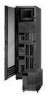
4. Cabling Your Server Use the following procedure to attach the cables to your Netfinity 5500 M10. 1 Select a location that will allow for air circulation. Be sure to maintain minimum clearances around the server: Front Rear Left and Right Sides 306 mm (12 in.) 306 mm (12 in.) 51 mm (2 in.) 2 Connect the device cables to the server. For the location of cable connectors, refer the illustrations on the following page. Important If you are attaching a modem or fax machine to the server and you are in the United Kingdom, plug in the power cords first; then, connect the telephone line to the wall outlet and the server. To connect the server 10BASE-T or 100BASE-TX port to a hub, use a UTP cable with RJ-45 connectors at both ends. An EIA/TIA-568 category 5 cable must be used for 100BASE-TX connectors to meet various standards, including electromagnetic compatibility. 3 Connect the power cord 1 to the server. 7 CAUTION: When the power-cord strain-relief bracket option is installed on the power cord, the server must be plugged into a power source that is easily accessible. 4 Remove the shipping screws 2 from the power supply. Important Your server might use a different handle and a blue thumbscrew instead of the handle and shipping screws shown in the illustration. 5 Install the power-cord strain-relief bracket 3 (if applicable). 6 Connect all power cords to electrical outlets. 7 Continue with "5. Verifying Your Server Is Operating Properly" on page 10. 8 Netfinity 5500 M10 Express Setup and Installation
-
 1
1 -
2
-
3
-
4
-
5
-
6
-
 7
7 -
 8
8 -
 9
9 -
 10
10 -
 11
11 -
 12
12 -
 13
13 -
 14
14 -
 15
15 -
 16
16 -
 17
17 -
18
-
19
-
20
 |
 |
