IBM 8676 Option Installation Guide - Page 21
Light Path Diagnostics panel
 |
UPC - 087944770107
View all IBM 8676 manuals
Add to My Manuals
Save this manual to your list of manuals |
Page 21 highlights
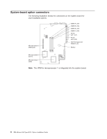
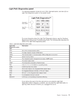
Light Path Diagnostics panel The following illustration shows the error LEDs, light path button, and test LED on Light Path Diagnostics panel on the system board. Light path button (SW1) Test LED (CR82) Light Path Diagnostics™ CPU VRM CNFG MEM SP PS TEMP FAN DASD PCI A PCI B PCI C NMI NON OPT For more information about the Light Path Diagnostics feature, see the Hardware Maintenance Manual and Troubleshooting Guide. The following table describes the LEDs on the Light Path Diagnostics panel. Table 1. Light Path Diagnostics panel LEDs Light Path Diagnostics panel LED Description CPU One of the microprocessors failed. VRM A voltage regulator module (VRM) failed. CNFG The microprocessor or microprocessor VRM configuration is incorrect. MEM System memory failed. SP The integrated system management processor (ISMP) failed. PS The power supply failed. TEMP The temperature exceeded a threshold level. FAN A fan (1, 2, 3, 4, or 5) failed or is operating slowly. DASD A SCSI hard disk drive failed. PCIA PCI-X slot 2 failed or the integrated SCSI adapter failed. PCIB An integrated Ethernet controller or PCI slot 1 failed. PCIC PCI slot 1 or the integrated video adapter failed. NMI A nonmaskable interrupt occurred. NON OPT A PCI bus is not operating at maximum efficiency. If you remove the server from the rack and you are using the Light Path Diagnostics LEDs to diagnose a problem, you can press the Light Path button to light any LEDs that were lit before you unplugged the server. Chapter 1. Introduction 9
-
 1
1 -
2
-
3
-
4
-
5
-
6
-
7
-
8
-
9
-
10
-
11
-
12
-
13
-
14
-
15
-
 16
16 -
 17
17 -
 18
18 -
 19
19 -
 20
20 -
 21
21 -
 22
22 -
 23
23 -
 24
24 -
 25
25 -
 26
26 -
27
-
28
-
29
-
30
-
31
-
32
-
33
-
34
-
35
-
36
-
37
-
38
-
39
-
40
-
41
-
42
-
43
-
44
-
45
-
46
-
47
-
48
-
49
-
50
-
51
-
52
-
53
-
54
-
55
-
56
-
57
-
58
-
59
-
60
-
61
-
62
-
63
-
64
 |
 |
